The David Hamel's Pictures Album
Courtesy of Tracy from the Hamel's Teamwork
created on September 18th, 1999 - JLN Labs - Last update September 21th, 1999
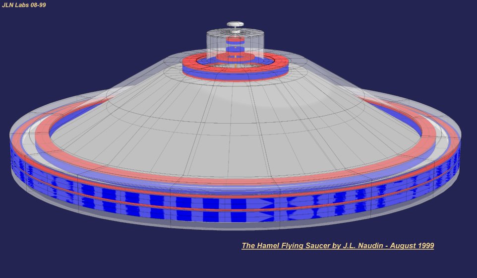
The Hamel's Flying Saucer (HFS) under construction


" The cone is all one piece. The horizontal wing surface is also one piece. Except for the top skin where I ran out of material I had to use two pieces attached to a piece of 3/4 inch plywood. There is also 3/4 inch plywood at the bottom with a three inch hole in the center and air holes around the bottom. There are no sections. The ribs on the horizontal wing portion are two 1/2 inch pieces of aluminum striping joined together with a brass screw and then glued with the 3m glue. They act as stiffeners. The cone stiffener is a round piece of 1/2 inch plywood half way down the cone and 1/2 inch aluminum strips from there to the horizontal portion of the wing. It's very light construction weighing only 34 pounds without the magnets, but sturdy and strong enough to hold the wings in place. It is my own design. " Tracy.

David Hamel working on his inner cones.

Inner Cones of the HFS.

" The top pic is David's current over-unity device. The bottom pic shows a large square portion of the bottom of the craft when David completes its assemble. I think he used this for something else at one time, but he said that this will go at the bottom where the iris is to be position. The corners will hold large pinions (size of bowling balls) of which the engine will be connected to using extensions from the wings that will cause this plate to also vibrate. At least that's the way I understand the last phase of the craft. " Tracy.

" The
top pic shows the 2 x 4 x 6 inch magnets David had me install to
give the wings more lift. There are 18 on one side of the wing
and 18 on the underside each in rejection to each other held in
place by the brackets. David had marked then all with a large N
so I wouldn't get them mixed up. I was too busy trying to keep
the damn things together and in place to notice what method he
used to mark the magnets. The center part with the rod sticking
up is to hold the wings in place. I welded a small bracket to
each wing so the rod could slide all the way through when the
wings were stacked. You can see the bottom part of the structure
of which the bottom wing rests on. Stainless Steel channel was
used to hold the magnets in place and all are the standard
rectangle magnets from AZ Industries with the indentations facing
towards the opposing magnets face to face. On the wing which you
can't see is another row of magnets directly underneath the row
that you can see. All of these are also indented side facing
indented side in rejection.
The bottom pic shows the wing on the table before we moved it.
" Tracy.

" This is the photo that Bob Thomas was so nice to send me that he received from David. Please note the channel where the magnets are attached to. On his wings, there is no channel whereas the magnets are pop riveted directly to the skin. I will try to get Bob to explain more fully via e-mail the set up of the photo. I believe this piece has been placed on David's living room table." Tracy.

" These are two pics that I took summer of 98 while I was working on David's current engine.The measurement on the bottom pic from point of the triangle measures exactly 8 feet. This is where the pinions go. The overall diameter is something like 9 and 1/2 feet whereas mine is 4 feet. The fellow next to David is a friend of his who helps him on Saturdays." Tracy

" Top photo
shows where I welded the piece of pipe to hold the long spike
that keeps the wings lined up so they don't move when assembling
the rest of the machine. This is a very important item and must
be done exactly or else the wings magnets will not be in
rejection when the top wing is resting above the bottom wing. If
the wings go to far from one side to the other the magnets will
come into attraction and lock up. The length of this movement is
restricted by the pinions. There are spikes in front of all three
cups as pictured in the photo.
Bottom photo shows the rectangle magnets being placed on the
bottom plate of the machine. You will notice there are no
perimeter magnets at the very bottom or the very top leaving the
two wings in between which has the perimeter magnets. The heavy
looking rectangle piece on top of the cups is to hold the
measuring triangle in place so that all magnets are placed
exactly where they are suppose to go. All magnets are pop rivet
with stainless steel pop rivets and you want to be sure to
measure 3 or 4 times before you pop rivet that little puppy into
place because they are very hard to grind off should you make a
mistake." Tracy.


These 3 cones are about 10' dia. It will make
up the top section. The next
" Section will be 20 ft.
and the next 40'. Photos include Mr. Hammel, his
workshop and a closeup of the magnets he is using. "
Photos sent by duesouth@iname.com (woody)
The Hamel's Drum under construction

" The
top pic shows Bob Thomas's drum on the left and my insert on the
right which I later used to go inside a 55 gallon drum. The
insert fits into the steel drum after you cut off 1/2 inch off
the top so you and reqlue it back on. Bob cut some peek holes in
the side of his drum so he could watch it oscillate. I had done
the same only at the top.
The bottom pic shows the inside of Bob's steel drum. " Tracy.
 .
.
" The upper left is the driver for Dan Dial's eight foot Modified Telsa Coil. The upper right shows Dan pointing a neon tube towards the top and watching it light up as it gets close to the coil. The bottom shows Dan's patent device which he describes in the visit message a few days ago." Tracy.
See Also:
The Hamel devices and Tests ( pictures album ) by Tracy Jones ( updated 09-23-99 )

![]() Mail to Tracy or to JNaudin509@aol.com
Mail to Tracy or to JNaudin509@aol.com
Return to Hamel Technologies home page