3 September 2001. Thanks to BH.
Main text only, Annexes in preparation.
[116 pages, main text; 202 pages, annexes.]
FOR OFFICIAL USE ONLY
CJCSM 6231.05A
2 November 1998
MANUAL FOR EMPLOYING
JOINT TACTICAL
COMMUNICATIONS
JOINT COMMUNICATIONS SECURITY
JOINT STAFF
WASHINGTON, D.C. 20318
FOR OFFICIAL USE ONLY
CHAIRMAN OF THE JOINT
CHIEFS OF STAFF
MANUAL
J-6
DISTRIBUTION: A, B, C, J |
|
CJCSM 6231.05A
2 November 1998 |
MANUAL FOR EMPLOYING JOINT TACTICAL COMMUNICATIONS
JOINT COMMUNICATIONS SECURITY
References: See Appendix J.
1. Purpose. This manual provides a brief description of the COMSEC
equipment and outlines COMSEC procedures for operating the common baseline
circuit switch network, MS network, CNCE, theater data networks, and
point-to-point circuits. The following major topics are addressed:
a. Security information for system planners---circuit switch and point-to-point
circuits.
b. Security information for system planners---AN/TYC-39 MS and special data
circuits.
c. Security information for system planners---AN/TSQ-111 CNCE and transmission
systems.
d. COMSEC equipment description.
e. COMSEC procedures.
f. Keying concepts and management.
g. Joint Staff inter- and intratheater COMSEC package letters of instruction.
h. Data networking security equipment and procedures.
i. COMSEC equipment under development.
2. Cancellation. CJCSM 6231.05, 13 October 1995, "Joint Communications
Security," is canceled
3. Applicability. This manual applies to:
a. The combatant command or JTF J-6 directorate (or equivalent office)
responsible for joint communications management in a deployed JTF.
b. Components and the assigned joint communications support organization
in a JTF.
4. Request for Changes. Submit recommended changes to:
Joint Interoperability and Engineering Office
Attn: JEBBB
Fort Monmouth, NJ 07703-5613
5. Summary of Changes
a. Circuit switch COMSEC procedures were updated to include the CBCS. As
these procedures are moved to the main body of the text, procedures for legacy
configurations and equipment have been moved to the appendixes.
b. Instructions for ITSDN security were added.
c. NES security guidelines were added.
d. Information about equipment under development was added.
e. Information about the KIV-7 was added.
f. Information about strap and switch settings for specific key generator
applications was added.
g. New Joint Staff ICP letters of instruction were added.
6. Releasability. This manual is approved for limited release. DOD
components (to include the combatant commands) and other Federal agencies
may obtain copies of this manual through controlled Internet access only
(limited to .mil and .gov users) from the CJCS Directives Home
Page--http://www.dtic.mil/doctrine/jel.htm.
Joint Staff activities may access or obtain copies of this manual from the
Joint Staff LAN.
7. Effective Date. This manual is effective upon receipt.
For the Chairman of the Joint Chiefs of Staff:
[Signature]
DENNIS C. BLAIR
Vice Admiral, U.S. Navy
Director, Joint Staff
CJCSM 6231.05A
2 November 1998
MANUAL FOR EMPLOYING JOINT TACTICAL
COMMUNICATIONS
JOINT COMMUNICATIONS SECURITY
LIST OF EFFECTIVE PAGES
The following is a list of effective pages. Use this list
to verify the currency and completeness of your document. An
"O" indicates a page in the original document.
PAGE CHANGE PAGE CHANGE
i thru xii O D-1 thru D-2 O
I-1 thru I-26 O D-A-1 thru D-A-18 O
II-1 thru II-16 O D-B-1 thru D-B-4 O
III-1 thru III-28 O D-C-1 thru D-C-22 O
IV-1 thru IV-12 O E-1 thru E-6 O
V-1 thru V-10 O F-1 thru F-30 O
VI-1 thru VI-6 O G-1 thru G-10 O
A-1 thru A-12 O H-1 thru H-8 O
B-1 thru B-42 O J-1 thru J-4 O
C-1 thru C-22 O GL-1 thru GL-12 O
RECORD OF CHANGES
[None; form omitted]
TABLE OF CONTENTS
CHAPTER
I INTRODUCTION
General
RED/BLACK Isolation
Traffic Flow Security
Security Information for System Planners,
Circuit Switch and Point-to-Point
Circuits
Security Information for System Planners,
AN/TYC-39 and Special Data Circuits
Security Information for Systems Planners,
AN/TSQ-111 CNCE and Transmission Systems
Physical Security
Emergency Plan
Declassification Procedures
Interface Planning Checklists
Additional Information
II KEYS
General
Key
Rekeying Keys
V-key (V)
Net Keys (X-Keys)
Z-Key
Reentry Home Key (M, RH, or R)
Compartmented Key (S-Key)
Trunk Traffic Key (T)
Bulk Transfer Key (BT)
VINSON Cryptonet Variable (CNV)
VINSON Rekey Variable (RKV)
Manual Cooperative Variable Transfer (MCVT)
(DSVT-to-DSVT)
Joint Staff Intertheater COMSEC Package
Key Management
III CIRCUIT SWITCHING NETWORK COMSEC EQUIPMENT AND PROCEDURES
Introduction
AN/TTC-39( )
Mobile Subscriber Equipment
Unit Level Circuit Switches
CBCS Data Base Considerations
AN/TTC-42 Data Base Construction
Co-Parent and Alt-Parent Procedures for ULCS
Keys and Key Management
Key Assignments Within the HUS
Load TED to TED (Trunking)
Tactical-Strategic Interface
Protected Distribution Systems and Approved Loops
Dial-Up Message Switch Connectivity
Point-to-Point Operation (DSVT-to-DSVT)
STU-III Operation in Tactical Networks
Operation of the Motorola MMT/DNVT
Subscriber Terminal in Tactical Switches
Use of LKGs in Circuit Switch Calls
IV MESSAGE SWITCHING NETWORK COMSEC EQUIPMENT AND PROCEDURES
Introduction
Joint Staff ICP Pair-Wise Unique Key Tape System
KG-83 Certification
Assign Keys for the Local Loops
Loading KG-82s and KG-84()s
Rekeying a KG-84()
Loading KG-82 to KG-82 (Trunking)
External Interface (AUTODIN)
Point-to-Point Operation KG-84A to KG-84A
Message Switch Traffic Flow Security
Y-Community Traffic
AN/TYC-39 Reports Classification
V AN/TSQ-111 COMMUNICATIONS NODAL CONTROL ELEMENT AND
TRANSMISSION SYSTEM COMSEC EQUIPMENT AND PROCEDURES
Introduction
General
COMSEC Controller
Key Management
Key Generation and HUS Assignment
DOW Point-to-Point Operation (KG-84()-to-KG-84())
Manual Cooperative Variable Transfer (DSVT-to-DSVT)
Transmission Systems COMSEC Procedures
VI DATA NETWORK SECURITY
General
Security Policy Considerations for JTF to IP
Network Connectivity
NIPRNET Policy
SIPRNET Policy
Application of SIPRNET Policy
SIPRNET Access Limitations
JWICS Policy
[Annexes in preparation]
APPENDIX
A KIV-7 Embeddable KG-84 COMSEC Module
B Detailed COMSEC Procedures
C Equipment Descriptions
D Joint Staff Intertheater and Intratheater COMSEC
Package Letters of Instruction
Annex A--Letter of Instruction for Joint Staff
Inter- and Intratheater Circuit Switch
Network Key System, USKAT-C5572
Annex B--Letter of Instruction for The Use of
The Intertheater COMSEC Package Pair-Wise
Unique Keying Material
Annex C--Draft Letter of Instruction for Joint
Staff Inter- and Intratheater Circuit Switch
Network Key System, USKAT-C5572
E Future Equipment Descriptions
F KG-84() Family Applications
G Trunk Encryption Device Applications
H Network Encryption System
J References and Supplemental Reading
Part I-- References
Part II-- Supplemental Reading
GLOSSARY
Part I-- Abbreviations and Acronyms
Part II-- Terms and Definitions
FIGURE
I-1 CJCSM 6231 Manual Series
I-2 Generic Joint Task Force Communications Systems
III-1 Required Keys for A CBCS Network
III-2 Example CBCS Network
III-3 Typical Red Switch Connectivity
III-4 Possible Red Switch Connectivity
III-5 Example Red Switch Interswitch Trunk Connectivity
III-6 PDS Call Combinations (1 of 3)
III-7 PDS Call Combinations (2 of 3)
III-8 PDS Call Combinations (3 of 3)
IV-1 Representative Joint Message Switch Network
V-1 Data Orderwire to AN/TSQ-111
V-2 Representative Joint Transmission Network
A-1 KIV-7 Front Panel
A-2 KIV-7 Interconnectivity Diagram
B-1 KYX-15 Register Fill
F-1 KG-84A Internal Strapping for MRVC Interface to DRSN
F-2 KG-84A Front Panel Settings for MRVC Interface to DRSN
F-3 KG-84A Internal Strapping for ITSDN Interfaces
F-4 KG-84C Settings for Use With AN/MSC-63A
F-5 Unbalanced RED I/O and BLACK CD Connections
for Wireline Applications
F-6 Unbalanced RED/BLACK I/O Cable Configurations
for Land Based Applications
F-7 KG-84A RED and BLACK Connections for RS-232
F-8 KG-84A BLACK Connections to TRI-TAC (Wireline CD Mode)
F-9 KG-84A RED AN/UYK-83, RS-232 Synchronous
F-10 KG-84A RED Connection to AN/UGC-129
F-11 KG-84A (RS-422 RED and RS-449 BLACK) Connection to IDNX
G-1 IDNX Balanced RS-422 to KG-94A RED
H-1 NES Tower Configuration
H-2 Typical NES Interconnect Using an 802.3 to 802.3 Interface
TABLE
I-1 Circuit Switch Planning Checklist
I-2 Message Switch Planning Checklist
I-3 CNCE/Transmission Planning Checklist
II-1 Summary of Key Requirements
II-2 Subscriber Rekey Key Terminology
II-3 Interswitch Rekey Variables
II-4 Subscriber Net Key Terminology
II-5 Key Cross Reference List
III-1 CBCS COMSEC Complements
III-2 TEDs Available Normal-Through, by DTG
III-3 Recommended Storage Locations for CBCS Optional Keys
III-4 CBCS Storage Locations for Preassigned Keys
III-5 AN/TTC-42 HUS Allocations
III-6 CBCS Allowable Calls
IV-1 LKG and HUS Allocation
V-1 AN/TSQ-111 COMSEC Items
V-2 DOW Rules
V-3 LKG and HUS Allocation
V-4 Transmission Equipment COMSEC Complement
A-1 KIV-7 RED Interface Pinouts
A-2 KIV-7 BLACK Interface Pinouts
B-1 VINSON OTAR Procedures
C-1 Switch Commands and Functions
C-2 Center-Tap Strapping Options
C-3 Receive Cipher Text Clock Phase Selection
C-4 External Command Strapping
C-5 Resync (T) Command Termination Strapping (E-GFW PCB)
C-6 Resync (W) Level Logic Strapping (E-GFV PCB)
C-7 Resync (W) Timeout Strapping Options
C-8 Status Signal Voltage Strapping Options
C-9 KY-90 Technical Characteristics
D-1 USKAT-C5572 Key System
D-2 Key Terminology by Switch Family
D-3 New Key Labels and Old Key Labels
E-1 Release 0 STE Capabilities
E-2 Strapping Options for KG-184A A5 and A7 Boards
E-3 Strapping Options for KG-184C A5 and A6 Boards
F-1 KG-84A Switch Settings for Use with AN/UGC-74A
F-2 KG-84A Switch Settings for Use with AN/UGC-129
F-3 KG-84A Switch Settings for Use with Various
Terminals, Diphase Modem Interface
F-4 KG-84C Switch Settings for Use with AN/MSC-63A
F-5 KG-84C Switch Settings for Use with PC Terminals
F-6 KG-84A Switch Settings for ITSDN Interfaces
F-7 Simplex Operation, Autophase Enabled
F-8 Duplex Independent Operations
F-9 Duplex (End Around Sync) Operations
F-10 Strap Settings, HF Operation
F-11 KG-84A Switch Settings (SUN Workstation (or
Other) Using Wireline CD )
F-12 KG-84A Switch Settings (SUN Workstation (or
Other) Using Dedicated Modem or Dial-up)
F-13 Strapping Options for SUN Workstation Applications
F-14 Balanced RED I/O Cable Configuration for Maritime Applications
F-15 Balanced BLACK I/O Cable Configuration for Maritime Applications
F-16 KG-84() Concealed Controls for DOW Operation
F-17 KG-84A Strapped for Balanced DOW Operation
F-18 KG-84A Internally Strapped for Unbalanced DOW Operation
F-19 KG-84C Strapping Options
F-20 KG-84C Strap Settings, Operation with KG-84A
F-21 Strapping Options for KG-84A Used with KG-84C,
Nonconditioned Baseband, Unbalanced
F-22 Strapping Options for KG-84A Used with KG-84C,
Nonconditioned Baseband, Unbalanced, KG-84 Mode
F-23 KG-84A Switch Settings for Use with KG-82
F-24 KG-84C Switch Settings for Use with KG-82
G-1 KG-94()/-194() Strapping Options for the
AN/TRC-170, AN/TTC-39A(V)/D, AN/TYC-39(),
AN/TSQ-146, AN/TSQ-111, AN/TTC-42,
AN/TTC-46, AN/TTC-47, AN/TTC-48, SB-3865,
and GMF Satellite Terminals
G-2 TED Strapping Options, MS-CS DTGs
G-3 TED Strapping Options for IDNX
G-4 KG-194() Strapping Options for Maritime Applications
H-1 NES Component Classification and Marking
CHAPTER I
INTRODUCTION
1. General. This manual provides information about the
COMSEC aspects of the joint task force (JTF) backbone
network. Information presented in this document should be
used in conjunction with information contained in other
publications in the CJCSM 6231 series (Figure I-1). The
information in this publication primarily pertains to COMSEC
equipment most likely to be found in the JTF backbone
network. Figure I-2 is a guide for determining where to
find this equipment and the connectivity requirements.
TRI-TAC developed COMSEC equipment provides secure voice and
data traffic with a capability for electronic key generation
and distribution under processor control. Alternatively,
keys may be distributed using manual procedures. COMSEC for
equipment fielded later, like MSE, uses the same principles
and is completely interoperable with TRI-TAC equipment.
Operators and maintenance personnel associated with the
COMSEC equipment and keys described in this publication must
have a security clearance and need to know commensurate with
the level of classification of the equipment or keys
involved.
a. When the TRI-TAC COMSEC equipment was designed, the
term "variable" was used instead of the term "key."
However,"variable" was phased out and replaced by "key."
The term "variable" is embedded into the design of the
TRI-TAC equipment and is still used in conjunction with
specific commands associated with COMSEC functions.
Throughout this document, both terms are used and are
interchangeable. Equipment developed later (for example,
MSE and the AN/TTC-39D) use the term "key" primarily but may
use "variable" in certain applications. Where applicable,
tables of equivalents are shown.
b. COMSEC doctrine for TRI-TAC equipment use is
outlined in KAO-193A/TSEC, SAM-70, and NTISSAM COMSEC/1-87.
Similar MSE procedures are described in the MSE Key
Management Plan. Definitions of many of the terms found in
this document are contained in NSTISSI 4009. Definitions
presented in Part II of the Glossary are either not found in
NSTISSI 4009 or are expanded and tailored to the
applications found herein.
_____________________________________________________________
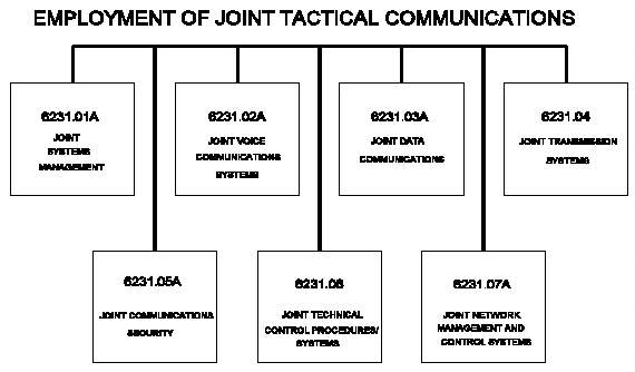 Figure I-1 CJCSM 6231 Manual Series
_____________________________________________________________
Figure I-1 CJCSM 6231 Manual Series
_____________________________________________________________
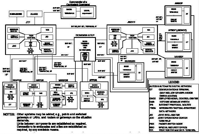 Figure I-2 Generic Joint Task Force Communications Systems
_____________________________________________________________
2. RED/BLACK Isolation. Personnel planning for and setting
up secure communications facilities must be aware of the
requirement for requisite RED/BLACK isolation. (In this
manual, the terms RED and BLACK (all capital letters) refer
to the TEMPEST connotation. Other implications of the words
red and black may appear.) The RED/BLACK concept pertains
to the separation of electrical and electronic circuits,
components, equipment, and systems that handle classified
plain text (RED) information in electrical signal form from
those that handle unclassified (BLACK) information in the
same form. The RED designation is applied to telecom-
munications and automated information systems, plus
associated areas, circuits, components, and equipment that,
when classified plain text signals are being processed,
require protection during electrical transmission.
Conversely, the BLACK designation applies to telecom-
munications and automated information systems and to
associated areas, circuits, components, and equipment that
process only unclassified signals. (COMSEC-encrypted data
are unclassified.) RED signals are any telecommunications
or automated information system signals that would divulge
classified information if recovered and analyzed. RED
signals may be plain text, key, subkey, initial fill,
control, or traffic flow related information. A BLACK
signal is any signal (including control or enciphered
signals) that would not divulge national security
information if recovered and analyzed. Refer to
NSTISSI 7000 and "National Security Telecommunications and
Information System Security TEMPEST/2-95" for RED/BLACK
requirements. TEMPEST guidelines for KG-84() installation
are found in Appendix F.
3. Traffic Flow Security. In addition to proper security
for classified communications, traffic flow security is
required also. Traffic security is the specific encryption
of traffic to protect the classified information contained
therein, while traffic flow security is protection that
conceals the presence of valid messages on communications
circuits, whether those messages are encrypted or not.
Traffic flow security is normally achieved by making the
circuit appear busy at all times. In tactical networks,
KG-94()/194() trunk encryption devices (TEDs) are used for
this purpose. This is the main purpose of TEDs, though they
are also used as primary traffic encryptor in a variety of
applications including MSE SP DNVTs. KG-82s and KG-84-based
COMSEC equipment can perform full-period encryption and
provide traffic flow security for individual circuits;
however, all digital transmission groups (DTGs) in the JTF
network will also be secured by TEDs. (KG-84-based
equipment refers to the KG-84A, KG-84C, KIV-7, and KIV-7
HS.) TEDs are part of the equipment suite of all tactical
switching facilities. Transmission facilities also have
TEDs, as indicated in Table V-4.
4. Security Information for System Planners, Circuit Switch
and Point-to-Point Circuits. This paragraph helps system
planners in developing security requirements for circuit
switches. Common baseline circuit switches (CBCSs) assign
COMSEC ID locations for all required keys automatically;
only optional keys require assignment by the operator.
Switches that have not been modified for CBCSs require all
keys to be assigned. Additionally, key usage for some keys
is different in unmodified AN/TTC-39As than in CBCSs. The
procedures below can be used to formulate the requirements
for the JTF secure voice switching network. Differences
between CBCSs and non-CBCSs are noted when applicable.
Chapter II explains key designations and use. The
procedures outlined below are normally done in conjunction
with the development of a circuit switch database. See
CJCSM 6231.02A.
a. Traffic Security. Determine the highest classi-
fication of voice traffic to be processed by the circuit
switch (CS). (This classification is normally SECRET.)
b. Certification. Check the KG-83 or KGX-93/93A
certification. Security guidance requires that these
devices be certified at random intervals not to exceed
1 year, when moved to a higher classification application,
after maintenance, or when administratively decertified for
storage. They are classified CONFIDENTIAL when not
certified. When certified, this equipment will be treated
as TOP SECRET until placed in operation. Once installed,
they will assume a classification level equal to the highest
classification level of the keys to be generated. Detailed
test procedures for certifying the KG-83 with the KT-83 and
performing KG-83 self-test are contained in the SAM-70
Maintenance Manual.
c. Digital Subscriber Voice Terminals (DSVTs).
Identify subscribers who need secure voice including those
who have a need for S-key operation and classmark the DSVTs
for these subscribers. (See CJCSM 6231.02A.) This is done
automatically in CBCSs. U-net keys 24 and 25 (stored in
hardened unique store (HUS) locations 26 and 27) support
TS/SCI CBCS subscribers that communicate with the
AN/TYC-39A. S-keys are pre-positioned on tape. CBCSs
permit digital nonsecure voice terminal (DNVT) subscribers,
in certain circumstances, to communicate in a secure mode.
See subparagraph 4q.
d. Telephone Numbers. Assign directory numbers to
subscribers assigned DSVTs, if they are not already assigned
on an affiliation list or preaffiliation list.
AN/TTC-39A(V)1s and AN/TTC-42s require a directory number
entry in conjunction with a COMSEC ID.
e. Assign Variable Locations. In non-CBCSs, assign a
COMSEC ID to a directory number of the rekeying key. Assign
a COMSEC ID for the common X-net key to the directory
number. Repeat this for all secure voice subscribers.
Location 0000 is reserved for the switch operation and
cannot be assigned for subscribers or an interswitch
rekeying key. CBCSs automatically assign subscriber COMSEC
IDs automatically. See Chapter III for details on key
assignments. The system planners should have assign
variable location (AVL) worksheets to depict the information
to appear on the screen display. These are contained in
CJCSM 6231.02A.
f. Assign Reentry Home (RH) Key. The M key is unique
to one area code and is assigned automatically in CBCSs.
The RH is used in unmodified AN/TTC-39As and must be
assigned on the AVL screen. The R key for the AN/TTC-42 is
unique per switch and is generated locally.
g. Assign Common Interswitch Rekey Key (CIRK). The
CIRK is a common key held by all switches in the same area
code of a joint network and is used to encrypt per-call keys
(V) between switches. The CIRK is usually held on paper
tape and must be pre-positioned by the controlling authority
at each switch location. The KOI-18 tape reader can be the
fill device for this application. As an option, hard-copy
key may be loaded from a KOI-18 into a KYK-13, KYX-15, or
AN/CYZ-10, then loaded into the remote switches. (For some
applications, this key is bulk transferred or locally
generated and not held on paper tape.) COMSEC ID locations
for the interswitch keys are discussed in later chapters;
the CIRV is assigned to location 0001. For proper
operation, the CIRV must be assigned in the database and the
hardware (Automatic Key Distribution Center (AKDC)) of non-
CBCSs (CBCSs do this automatically). This rule must be
followed even for a stand-alone switch that has no
requirement for interswitch key transfer.
h. Assign Interswitch Rekeying Variables. The unique
interswitch rekey variable (UIRV) is held on a switch-pair
basis and used only in AN/TTC-42s (called a UISRV). It is
used to transfer a variety of keys between switches. The
area interswitch rekey key (AIRK) is a common key for a
given pair of area codes. It will be held by the gateway
switches connecting that pair of area codes. If deployments
call for more than one area code, the AIRK must be assigned
and used to encrypt and decrypt per-call keys (V)
transferred between area codes. In CBCSs, the AIRK is an
optional key and must be assigned on the AVL screen.
Chapter III discusses COMSEC ID locations for the
interswitch keys; the AIRK assignments (based on the number
of area codes) will start at location 0130.
i. Local Loops. Identify the number of DSVTs
considered as local loops. A local loop is distinguished
from a long loop primarily by how the DSVT is initially
keyed--electronic or hard copy. These DSVTs can be serviced
with the U and M keys generated at the CS. The fill device
required to load the DSVT at these locations is either the
AN/CYZ-10, KYK-13, or KYX-15.
j. Long Loops. Identify the number of DSVTs considered
as long loops. Long loops are for terminals that are too
far from the servicing CS to permit timely transfer in a
fill device. These DSVTs must be initially serviced with X
and U keys generated from hard-copy key material. This key
may be held on paper tape. The KOI-18 can be used to fill
the DSVT directly or to load another fill device, which can
then be used to load the DSVT.
k. Trunking. Determine the digital trunk groups needed
for the circuit switched network. The T-key is a two-
holder, point-to-point key used to initialize the TEDs. It
is common to all TEDs in a trunk group. This key may be
held on paper tape, and the KOI-18 tape reader can be used
to load the TED directly or to load an AN/CYZ-10, KYK-13, or
KYX-15, which will then be used to load the TED. CBCSs use
a cold-start T-key (T i ) to initiate connectivity and permit
bulk transfer of operational T-key.
l. Tactical-Strategic Interface. The tactical-
strategic interface (to the Defense Red Switch Network
(DRSN))could either be a DSVT or equivalent at the strategic
end functioning as a long loop off the AN/TTC-39() or
interswitch trunks (ISTs) secured by KG-84()s. The type of
interface used is dependent upon the equipment available at
each end. In either case, hard-copy key material must be
pre-positioned at the strategic end. The keys required for
this application are the applicable U- and X- or M-keys.
m. Fill Devices. After the DSVT requirements have been
established, the system planner can allocate the fill
devices to support the mission. A general rule is one fill
device for each long loop and one fill device for every five
local subscribers. A KOI-18 tape reader is required at each
location where hard-copy key is positioned. A KYX-15 net
control device (NCD) or AN/CYZ-10 data transfer device (DTD)
is required for electronic transfer of key between switches.
One KYK-13 must be allocated to each DSVT that has S-key
requirements. One KYK-13 is usually allocated to each
mobile subscriber radiotelephone terminal (MSRT). The
AN/CYZ-10 DTD is replacing the other fill devices as it is
fielded. It has a higher storage capacity and may replace
one or more devices, depending upon the application. The
Joint Key Management System (JKMS), under development, will
facilitate distribution of keys to the DTD.
n. S-Key. Identify secure voice users who have a need
for S-key operation. The S-key is part and parcel of the
AN/TTC-39()'s complement of keys with actual use at the
subscribers' DSVT. It is not used by the CS. S-key
subscribers use hard-copy key material or an electronically
generated key normally generated by the AN/TYC-39 MS. If
using electronic keys, the fill device can be the KYK-13 or
AN/CYZ-10. If using hard copy, the KOI-18 tape reader is
required. The KOI-18 is normally used to load the KYK-13
associated with the DSVT. If the KYK-13 is used, it may be
left attached to the DSVT.
o. Security Classmark. When the circuit switch is
initialized, entries must be made to the database for each
secure subscriber. CBCSs do this automatically from
preaffiliation lists (PALs). Other switches must be
programmed. In the JTF backbone network, all DSVT loops
should be classmarked at least SECURITY PREFERRED.
p. Point-to-Point Circuits. Identify all secure
point-to-point voice circuits (DSVT-to-DSVT) and the
duration of the mission. The mission duration will
determine the number of keys, fill devices, and if rekeying
is needed. This is a non-TRI-TAC application and requires
only an X-key (different from the network X-key).
q. Approved Loops. Approved loops are also called
protected distribution systems (PDSs), defined in
NSTISSI 7003. CBCSs may be classmarked PDS Y or N. In
switches marked PDS=Y, DNVTs may be classmarked SECURITY
PREFERRED and handle secure calls. In the AN/TTC-39A(V)1,
analog or digital approved loops must be classmarked
SECURITY REQUIRED. The AN/TTC-42 and SB-3865 do not use
approved loops. However, calls from the AN/TTC-42 to or
from approved loops will be completed in the secure mode.
5. Security Information for System Planners, AN/TYC-39 and
Special Data Circuits. This paragraph provides information
on the AN/TYC-39 MS, subscriber terminals, AUTODIN access
lines, and trunks to formulate the security requirements for
a message switching network. Use the procedures below to
formulate these security requirements.
a. Traffic Security. Determine the highest
classification and category of traffic to be processed by
the AN/TYC-39 MS. This is normally TOP SECRET for
R-community switches and may include sensitive compartmented
information (SCI) for Y-community switches. (See
CJCSM 6231.07A.) Waivers exist to permit some types of
dial-up service through CBCSs.
b. Certification. Check the KG-83s certification. See
subparagraph 4b.
c. Subscriber Terminals. Identify the number of
subscriber terminals, including the Y terminals and mode of
operation for each. See the discussion in CJCSM 6231.03A on
terminal requirements. Assign HUS locations for each
terminal. These locations will store the rekeying U- and
X-traffic keys.
d. Trunks. Determine the number of trunks needed to
support the message switching network, and assign HUS
locations for each trunk circuit. Again, these locations
will store the rekeying U- and X-traffic keys for each trunk
circuit. Keying material must be pre-positioned at both
ends of the trunks, and equipment at these locations will be
initialized using keys from the Joint Staff Intertheater
COMSEC Package (JSICP) (See Appendix D).
e. AUTODIN. Determine the number of AUTODIN access
lines needed for the mission. Assign HUS locations for the
rekeying U- and X-traffic variables for each AUTODIN access
line. Keying material will be pre-positioned at designated
AUTODIN switches. The KG-84()s at these locations will be
initialized using JSICP keys.
f. Local Terminals. Identify the number of local
terminals. A local terminal is distinguished from a remote
terminal primarily by how the terminal is initially keyed--
electronic or hard copy. A local terminal can be initially
keyed with electronic keys generated at the AN/TYC-39.
Electronic keys for these terminals consist of the rekeying
key U and the X-traffic key. Keying devices required for
loading the KG-84 for local loops can be either the KYK-13,
the KYX-15, or the DTD. The system planner determines
whether a loop is a local or long loop by taking into
account the amount of time required for a courier to
transport the electronic key to the terminal. This is
determined by such factors as distance and terrain. Use of
electronic keys has the advantage of reducing the
requirements for hard-copy key.
g. Remote Terminals. Identify the number of remote
terminals. A remote terminal cannot be reached quickly by a
courier; therefore, it must be initially keyed using hard
copy U- and X-keys. The keying device used to load the
KG-84() at the terminal locations can be the KOI-18. As an
option, hard-copy key may be loaded from a KOI-18 into a
KYK-13, DTD, or KYX-15, then loaded into the remote terminal
equipment. The same hard-copy keys in paper tape form must
be pre-positioned at the AN/TYC-39 and the terminal
location. When no other prior arrangements have been made,
the servicing message switch has the ultimate responsibility
to ensure that remote subscribers have the proper key.
h. MASTER Switch-Crypto Net Control Station. Designate
a MASTER-crypto net control station (CNCS) switch for the
message switching network for controlling the distribution
of keying material. The system planners at the MASTER-CNCS
switch (JTF) location are responsible for the allocation of
hard-copy key material at other switches directly trunked to
the MASTER-CNCS switch. The MASTER-CNCS switch is
responsible for rekeying the COMSEC equipment supporting
these trunk circuits. The CNCS performs these functions for
the AUTODIN access lines.
i. Local Loop Keys. For each circuit identified as a
local loop, a unique rekeying U-key and an X-traffic key
must be generated and sent to these locations by courier.
j. Long Loop Variables. Each long loop circuit,
including subscriber terminals, AUTODIN access lines, and
trunk circuits, requires a unique U-key and a common X-sync
key pre-positioned at each location. Hard-copy key material
is required for long loops, and the keying device can be the
KOI-18 tape reader. As an option, hard-copy key may be
loaded from a KOI-18 into a KYK-13, KYX-15, or DTD, then
loaded into the remote terminal.
k. Fill Devices. After subscriber terminal, AUTODIN
access line, and trunk circuit requirements have been
established, the system planner should allocate the fill
devices needed to support the mission. The general rule is
one fill device for each long loop, and one fill device for
every five local subscribers. A KOI-18 tape reader is
required at each location where hard-copy key is positioned.
Key will not be stored in the KYK-13, KYX-15, or DTD for
more than 12 hours when that same key is stored in the
HGX-83 AKDC in the AN/TYC-39A.
l. Special Data Circuits. Identify the special
point-to-point (non-TRI-TAC) data circuits (KG-84() to
KG-84()). When the KG-84() is operated point-to-point with
another KG-84() on a full period circuit, the X-traffic key
can be extended to a 1-month cryptoperiod with daily
updates. When the X-key is used for the 1 month (or longer)
cryptoperiod, with daily updates, an update to update count
01 must be performed immediately after loading the key. A
U-key is not required when using the update function. Thus,
for point-to-point operation only the X-traffic key is used
with the KG-84()s. Depending on the mission requirement,
the X-traffic key can be generated by the AN/TYC-39A or
taken from hard-copy key material. In either case, identify
the number of point-to-point circuits to formulate
requirements for keys and keying devices.
6. Security Information for Systems Planners, AN/TSQ-111
CNCE and Transmission Systems
a. Traffic Security. Determine the highest classi-
fication of traffic that will use keys generated at the
CNCE. Data orderwires (DOWs) provide the CNCE with status
information gathered at each transmission assemblage or
multiplexer shelter. The DOWs are secured with KG-84()s or
KG-84()/KG-82 combinations. When the status information is
decrypted at the CNCE, this information is not classified.
Thus, status information can be treated as sensitive and
protected as CONFIDENTIAL. If approved loops are not
implemented, all traffic within the CNCE will be BLACK.
Therefore, traffic that is to be bulk encrypted by TEDs can
also be protected at the CONFIDENTIAL level. However, other
security requirements may necessitate a higher classi-
fication of keys than CONFIDENTIAL. (JSICP T-keys are
SECRET.) It is recommended that for all deployments, the
KG-83 assume the classification level of SECRET.
b. Certification. Check the KG-83 certification. See
subparagraph 4b.
c. Collocated DOWs (KG-82/KG-84()). Identify the
collocated DOWs. These DOWs are within transmission
assemblages that are collocated with the CNCE and are
secured with the KG-82(LKG)/KG-84() combinations. Assign a
HUS location and LKG to each collocated DOW. These
collocated DOWs require two keys per assemblage, which are
the key encryption key (KEK "U") and the traffic encryption
key (TEK "X"). The keys for these configurations reside in
the HUS location assigned to that particular assemblage.
Each collocated DOW assemblage must operate on its unique
keys as assigned within the HUS.
d. DOWs Operating Point-to-Point (KG-84() to KG-84()).
Identify the DOWs that operate point-to-point (KG-84() to
KG-84()) (see Figure V-1). These orderwires may be keyed
with pre-positioned hard-copy key or electronically
generated key depending on the distance and ownership. The
DOWs only require a traffic encryption key (TEK).
e. Fill Devices. After the DOW requirements have been
established, the system planner should allocate fill devices
needed to support the mission. For collocated DOWs one
KY-13 fill device (six addressable storage registers) is
needed for every three collocated DOWs. A KYX-15 may
replace one or more KYK-13s. DOWs operating point-to-point
(KG-84() to KG-84()) will require the KOI-18 tape reader at
each KG-84 location or the KYK-13 fill device if using
electronically generated key. DTDs may replace the KYK-13
and KYX-15 as they become available.
f. Traffic Flow Security. Each DTG terminating on an
AN/TTC-39 series CS or multiplex facilities should be
secured using a TED. Digital group multiplex (DGM) equip-ment
configurations that use the TED are discussed in
CJCSM 6231.04. Further, for analog groups, selected
transmission equipment, such as the AN/TSC-85B or -93B GMF
satellite terminals and the AN/GRC-201 tropo terminal use
K-94()s-194()s to provide bulk encryption. The system
planner should always ensure that each major DTG or analog
group is provided traffic flow security by a KG-94()/-194()
(see CJCSM 6231.04), as appropriate. This does not imply
that RED and BLACK information should be mixed in the same
group (although this is allowed in an MSE PDS). Encryption
for traffic security should be provided before the
information is multiplexed into a group. Avoid the use of
multiple TEDs on single transmission links where
operationally feasible. This recommendation is based on the
need to maintain simplicity in system keying,
initialization, and reinitialization procedures. If the
transmission equipment is collocated with the CNCE, bulk
encrypt within the transmission equipment. However if the
transmission equipment is remoted from the CNCE to a radio
park, by using a short-range radio system, then bulk encrypt
at the CNCE. These guidelines may be modified to account
for the availability of TEDs within various equipment
suites.
g. Approved Loops and Trunks. When implementing
approved loops connect directly to the circuit switch via a
PDS. If the interswitch trunks are classmarked AS (Terminal
Type 28) or the extraswitch trunks are classmarked AS and
are connected to the CNCE, operate as a RED CNCE. However,
if the inter-switch trunks are the digital nonsecure (DN)
(Terminal Type 29), then all traffic within the CNCE would
be BLACK. The AN/TTC-42 does not use analog secure trunks.
7. Physical Security. Physical security for the COMSEC
components of the JTF network will be in accordance with
Service procedures and the guidance contained in
subparagraphs a through g.
a. Access Controls
(1) Each person assigned to shelters containing
AN/TTC-39(), -42, -46, -47, -50, and/or AN/TYC-39 COMSEC
equipment and DTDs must have, as a minimum, a SECRET
clearance. TOP SECRET clearances are required if operation
personnel have access to TOP SECRET cryptoequipment,
cryptomaterial, electronic keys, or TOP SECRET plain text.
(2) Personnel with less than SECRET clearances,
whose duties require occasional access to the shelter (for
noncryptographic maintenance, repair, or housekeeping) will
be permitted entry only when continuously escorted by a
regularly assigned, appropriately cleared individual.
(3) Uncleared users may use the handset or headset
of the KY-68 or approved loops in the presence and under the
supervision of appropriately cleared personnel (US or other
national or international organizations to which the
equipment has been released (see CJCSI 6510.01)) provided
the distant party has been alerted to the participation of
an uncleared user.
(4) Military or civilian guards and security
patrols who provide area protection for the shelters do not
need be cleared but will not be authorized entrance. In the
event of an emergency, uncleared personnel including guards,
fire, police, or rescue personnel will be granted immediate
entrance to deal with the emergency (fire, flooding,
terrorist acts, etc.). Upon resolution of the emergency,
reporting actions IAW appropriate Service directives will be
completed.
b. Personnel Protection. The CS and/or MS shelters
that contain operating HGF-85 or -87, HGF-83, or HGF-93 or
-96, will normally be occupied by two cleared individuals.
Brief absences of one individual are permitted as authorized
by the local authority. The two-person rule does not apply
to the AN/TTC-42 when the restricted command locking bar is
in place. When TOP SECRET material is involved, the
requirement for two-person integrity (TPI) will be
considered. TPI is a handling and storing system designed
to prevent single-person access to certain COMSEC material.
TPI handling requires that at least two persons, authorized
access to COMSEC keying material, be in constant view of
each other and the COMSEC material that requires TPI
whenever that material is accessed and handled. Each
individual must be capable of detecting incorrect or
unauthorized security procedures with respect to the task
being performed. All DOD personnel are required to adhere
to TPI handling and storage for TOP SECRET key, except in
tactical situations (see NSTISSI 4005, paragraph 42c). TPI
is no longer automatically required for TS key in tactical
situations; however, the controlling authority for the
equipment and circuits must make the final determination.
Use of TPI is recommended whenever possible, especially in
SCI applications.
c. Shelter Locking Device. The access door shall be
secured with a three-combination changeable padlock, NSN
5240-00-285-6523 or equivalent, during periods of
nonoperation. To facilitate rapid reentry, the access door
may be secured with a good quality key-operated padlock when
operating personnel are absent for short periods of time.
When individual Service procedures do not authorize the use
of a three-position, dial type, changeable combination
padlock to secure such shelters, padlocks Service-specified
will be used. A key control system is then required.
d. Restricted Areas
(1) The operational CS or MS shelter will be
located in a restricted area. Access to a restricted area
is subject to special restrictions or controls for security
or to safeguard property or material. The following
combinations of security control should be considered in
setting the appropriate protection level: fences,
concertina wire, alarms, guards in the vicinity or acting as
perimeter security, identification and security check
procedures, entry control points, and escort procedures for
maintenance, repair, or housekeeping personnel. Examples of
appropriate combinations are: fences and alarms, fences and
guards, or fences and identification and security check
procedures.
(2) Each shelter will be operated as a limited
access area, consistent with the following:
(a) Access Restriction. Only personnel who
are required to be present to perform assigned duties will
be authorized access to the shelter.
1. The name of each authorized person
must appear on the access list maintained within the
shelter.
2. An official having cognizance over the
shelter must approve the composition of the access list,
including the addition of each new name.
3. Persons not named on the access list
who require access in the performance of their duties, such
as custodial and maintenance personnel, may be authorized
access only if they are under continuous escort by an
individual whose name appears on the access list.
(b) Visitors Register. The register should
show the date of visit, the name and signature of the
visitor, the visitor's title or rank and organizational
affiliation, the purpose of the visit, the name of the
authorizing officer, and the time in and out. A visitors
register may not be required by Service regulations.
e. Storage. The rules listed below apply generally.
Additional rules apply specifically to the storage
requirements and subsequent use of KG-83 and KGX-93/93A key
variable generators (KVGs). These rules are summarized in
subparagraph 7e(3). The rules are presented in more detail
in NAG-16D.
(1) Operational Site
(a) At an operational site, the unmanned
shelter constitutes an authorized storage facility for keyed
or unkeyed classified COMSEC equipment when the following
conditions have been met:
1. The shelter is secured according to
subparagraph 7c.
2. The shelter is located in a restricted
area as specified in subparagraph 7d.
(b) If the shelter has a security container
(not mandatory), fill devices including the DTD, hard-copy
keying material, and classified documents may be secured
therein.
(c) If the provisions of subparagraph 7e(1)
cannot be met, all COMSEC equipment will be zeroized, the
common fill devices (DTD) will either be zeroized or removed
and stored at an approved alternate site, and all hard-copy
keying material and all classified documents will be removed
and stored at an approved alternate site.
(2) Nonoperational Site
(a) At a nonoperational site, the shelter
constitutes an authorized storage facility for classified
COMSEC equipment contained therein when the following
conditions have been met:
1. The shelter is secured according to
subparagraph 7c.
2. The shelter is physically controlled
as specified in subparagraph 7d.
3. All COMSEC equipment and devices
stored therein have been zeroized.
4. The KG-83 (or the KGX-93/93A, where
found) has been placed in a GSA-approved security container.
As an exception, the KG-83 may remain in the shelter but the
rules listed in subparagraph 7e(3) must be observed.
(b) When the shelter cannot be located within
a restricted area, the commander must institute safeguards
that will preclude any reasonable chance of tampering,
unauthorized access, sabotage, or theft of the shelter and
its contents. Such measures should include periodic checks
by security guards or patrols and a sight inventory of the
contents of the shelter at least once each month.
(c) Storage of keys in the shelter is not
authorized at a site where communications operations are not
being performed (like a warehouse or a depot). All keys
must be removed from the shelter and all COMSEC equipment
and devices must be zeroized. Classified documents may not
be stored in the shelter at such a site.
(d) Whenever a shelter is not secured or
physically controlled as described in subparagraphs 7c and
7d, the tamper detect labels on KG-83s and KGX-93/93As must
be checked to ensure that there was no tampering before
using the equipment. If there is an indication of
tampering, the equipment must be replaced immediately and a
COMSEC incident reported. Rules governing the use of tamper
detect labels are contained in NAG-16D.
(3) KVG Storage. KG-83 and KGX-93/93A KVGs may be
stored in unmanned TRI-TAC and MSE shelters, if the
following conditions are met:
(a) Physical Safeguards. Safeguards described
in subparagraph 7e(2)(b) must be applied.
(b) Certification. Each KVG must have been
certified within 12 months, to the level of traffic for
which it must generate keys, by persons who are properly
cleared and technically qualified using a certified KT-83
and NSA-approved procedures.
(c) Tamper Detection Labels. At the time of
the last certification, NSA-furnished tamper detection
labels were applied to each KG-83 and KGX-93/93A IAW NSA
instructions.
(d) Locking Bars. Each KVG must be secured in
its mounting by means of a hinged locking bar on a TPI basis
by two combination locks.
(e) Inspections. All tamper detection labels
must be visually inspected by partially withdrawing the KVG
from its mount immediately before each KG-83 or KGX-93/93A
activation.
f. Transportation. Keying material and classified
COMSEC equipment need not be removed before transporting the
shelter. During movement, the facility must be locked and
escorted; escorts need not be armed but must be cleared for
the classification of the COMSEC material contained in the
shelter. The KG-83 or KGX-93/93A may be certified, and the
rules listed in subparagraph 7e(3) must be complied with
before the KVG can be used. Transportation of accountable
COMSEC material exclusive of the shelter will be IAW
guidance contained in appropriate Service regulations.
g. Reportable COMSEC Incidents. Any occurrence that
subjects any classified COMSEC material or equipment to
possible compromise must be reported immediately IAW
NSTISSI 4003 or appropriate Service, department, or agency
directives or regulations. Any suspicious or unusual
occurrence should be reported immediately. While these
conditions may or may not be compromising, they must be
reported for subsequent evaluation. COMSEC incidents are
reportable IAW NSTISSI 4003 and applicable Service,
Department, or agency directives or instructions.
8. Emergency Plan. In the event of threatened or imminent
overrun or capture, COMSEC keys, material, and equipment in
jeopardy of compromise will be collected and destroyed in
accordance with the following guidance as directed by local
commanders or their designated representatives. Periodic
emergency action exercises should be conducted to reinforce
the actions specified in this paragraph.
a. Each switch shelter and subscriber location will
contain an up-to-date listing reflecting all COMSEC and
other classified materials.
b. Destruction priority is as follows:
(1) Superseded and currently effective keying
material and equipment marked CRYPTO. This includes
zeroizing all module equipment, COMSEC databases, and fill
devices in use. All keying material and equipment marked
CRYPTO must be destroyed before any nonoperational test key.
(2) TOP SECRET multiholder keying material to be
used within the next 30 days.
(3) SECRET and CONFIDENTIAL multiholder keying
material to be used within the next 30 days.
(4) COMSEC maintenance manuals, operating
instructions, and general publications, or at least the
pages containing sensitive information.
(5) Classified printed circuit boards (PCBs) in all
module equipment.
(6) Any remaining classified COMSEC material,
including history tapes, future keying material not included
in items (2) and (3), and all COMSEC equipment and devices.
c. Materials described above will be destroyed in
accordance with approved methods. Appropriate facilities
like a burning pit with fuel, if required, will be put in
place during shelter setup.
d. One person per shelter per operating shift will be
delegated the responsibility for zeroizing all keyed
equipment and devices contained in that shelter. These
individuals will be charged with the destruction of any
superseded or unused hard-copy keying materials and COMSEC
aids contained in the shelter.
e. One individual per shelter per operating shift will
be delegated the responsibility for moving all history tapes
to the fire pit for destruction and witnessing the total
destruction of the material.
f. One person per shelter per operating shift will be
delegated the responsibility for physically destroying all
COMSEC equipment and devices contained in the shelter.
Physical destruction is herein defined as damaging the
equipment and devices to the point they are unusable. Use
any physical means available. For example, remove equipment
and smash or crush it with a sledge hammer or chop it with
fire ax.
g. Check off on the shelter COMSEC inventory listing
each item to be destroyed or zeroized to ensure nothing is
overlooked. The evacuating party should carry the inventory
listing.
h. Make all attempts to assess the extent of material
compromised by an overrun. Use methods such as review of
documents, physical observation, or interviews of survivors.
Local commanders or their designated representatives will
submit required reports to the proper authorities.
i. The emergency plan will be posted in each shelter,
and all personnel will be familiar with its contents. The
duty position of personnel specifically delegated
destruction responsibilities will be listed on the emergency
plan.
9. Declassification Procedures. Safeguarding classified
information in a computer or computer system requires
special precautions because of the type of storage media and
devices (magnetic drums, disks, disk packs, and tapes) used
to store, record, or manipulate data that must be protected
by appropriate classification and security controls until
the declassification procedures below are carried out. The
eventual temporary or outright release of the storage device
or a system including storage media should be anticipated.
Procedures to release or deploy the storage media outside
the controlled environment are below. Destruction may be
used when the media is no longer needed or the risks
associated with declassification are unacceptable. See
NSA/CSS Manual 130-1, Annex D, for further guidance.
a. Magnetic Tapes. Tapes used to store magnetically
recorded digital data may be declassified by erasing with
bulk tape degaussers. These degaussers must be tested and
approved by a DOD component or a commercial testing
laboratory. Such tests may be certified by adhering to test
methods and performance criteria outlined in NSA/CSS
Specification L1-MTC-4A, "Magnetic Tape Degausser." DOD
components may, where necessary, develop procurement
specifications for their use, provided test methods and
performance criteria comply, as a minimum, to the NSA/CSS
specification outlined above. The degausser must be listed
in the NSA Information Systems Security (ISS) Products and
Services Catalog as meeting minimum requirements for
degaussing the media.
b. Magnetic Disks, Disk Packs, Drums, and Other Similar
Rigid Magnetic Storage Devices. The equipment will be
checked immediately before beginning the overwrite procedure
to ensure that malfunctions do not occur that will prevent
the classified information from being effectively over-written.
Thereafter, all storage locations will be over-written
a minimum of three times, once with the binary digit
"1," once with the binary digit "0," and once with a random
numeric, alphabetic, or special character. The overwrite
must be verified by testing of at least 10 percent of the
overwrite. Such alphanumeric or other unclassified data
will be left on the device. The electrical current used in
overwriting must be equal to that used in recording the
information but of a strength that will not damage or impair
the equipment. Only use evaluated and approved overwrite
programs. The risks associated with software overwrite
procedures may be unacceptable considering data sensitivity,
ultimate disposition of the media, and possible inherent
weakness of the procedures. Software overwriting is not
authorized for declassification of COMSEC keying material
marked CRYPTO.
c. Inoperative Magnetic Disks, Disk Packs, Drums, and
Similar Rigid Storage Devices. The storage device may be
declassified by exposing the recording surface(s) to a
permanent magnet. The magnet should be listed in the NSA
ISS Products and Services Catalog as meeting minimum
requirements for degaussing the media.
d. Internal Memory. Volatile memory can usually be
declassified by removing all power, including battery and
capacitor power supplies.
10. Interface Planning Checklists. The planning
information in this chapter has been summarized in three
checklists--Tables I-1, I-2, and I-3. These checklists are
not meant to be all-inclusive and should be modified for
local use. These checklists should be used in conjunction
with equipment worksheets found in CJCSMs 6231.02A and
6231.03A. In some cases, applicable worksheets are
identified on the checklists. Be sure to classify completed
checklists at the appropriate level if classified
information is entered in the remarks.
11. Additional Information. Information contained in this
manual may change after publication but before the next
revision. Several organizations maintain home pages that
contain the most current information and additional related
information. Information pertaining to switch software and
related procedures is maintained by EA-TSS at the following
addresses:
http://EATSS1.SED.MONMOUTH.ARMY.MIL and
http://EATSS.CECOM1.ARMY.SMIL.MIL
The software engineering directorate home page is found at:
http://WWW.SED.MONMOUTH.ARMY.MIL
Information about test results, lessons learned, and other
information about tactical circuit switch testing is
maintained by the Joint Interoperability Test Command at:
http://JITC-EMH.ARMY.MIL and
http://207.132.160.252/HONOR/JITC.HTM or
http://199.208.204.125/JITC.HTM
The Joint Communications Support Element maintains current
information relevant to its operations at:
http://WWW.JCSE.MACDILL.AF.MIL
The Air Force "Index of Deployable C4I" is found at:
http://www.afca.scott.af.mil/seminars/xpxrman/indexp.htm
The Army Signal Command home page is located at:
http://138.27.190.13/ASC_MAIN.HTML
Network management information may be found at:
http://www.gordon.army.mil/tsmnm
_____________________________________________________________
Table I-1. Circuit Switch Planning Checklist 1/, 2/
Task Yes No Remarks
_____________________________________________________________
Switch _______/Location _______
KG-83s or KGX-93/93A Certified
_____________________________________________________________
DSVTs (all)
Requirements Identified
Local/Long Loops Flagged
Keys, Fill Devices Allocated
Classmarks Assigned (AAL, APL,
ATS 3/)
Directory Numbers Assigned (ATS
3/)
COMSEC IDs Assigned (AVL 3/)
RH Key Assigned (AVL 3/)
S-Key Users Identified
Key Material Allocated
Fill Devices Allocated
_____________________________________________________________
Trunks (all)
Keys Identified, Positioned
CIRV Assigned (AVL 3/)
Other IRVs Assigned (AVL)
TEDS
Required/Assigned (ADT)
Keys Allocated
_____________________________________________________________
Strategic Interface
Type (Long Loop or IST)
Keys Identified, Positioned
_____________________________________________________________
Message Switch Trunks (all)
Keys Assigned (AVL)
TED Assigned (ADT)
_____________________________________________________________
STU-IIIs
Users Identified
Connectivity Established
_____________________________________________________________
Point-to-Point Circuits
Keys, Fill Devices Assigned
__________
1/ To be completed for each switch.
2/ Applicable AN/TTC-39( ) worksheets in parentheses.
3/ Apply only to AN/TTC-39A(V)1s and AN/TTC-39A(V)4s that
have not been converted to CBCSs. See Chapter III and
CJCSM 6231.02A.
_____________________________________________________________
_____________________________________________________________
Table I-2. Message Switch Planning Checklist 1/
Task Yes No Remarks
_____________________________________________________________
Switch _______/Location _______
MASTER/CNCS?
_____________________________________________________________
Traffic Security Level
_____________________________________________________________
KG-83s Certified
_____________________________________________________________
Subscriber Terminals (all)
Identified
HUS Locations Assigned
_____________________________________________________________
Trunks
Number required at this switch
Distant End(s) Identified
Key Material Identified,
Positioned
HUS Locations Assigned
_____________________________________________________________
AUTODIN Access Lines
Number Required
Key Material Identified
HUS Locations Assigned
_____________________________________________________________
Local Loops (all)
Keys Identified, Generated
Fill Device Identified
_____________________________________________________________
Long Loops (all)
Key Material Identified,
Positioned
Fill Device Identified
_____________________________________________________________
Special Data Circuits, This
Location
Keys Identified
Fill Device Assigned
_____________________________________________________________
1/ To be completed for each switch or location.
_____________________________________________________________
_____________________________________________________________
Table I-3. CNCE/Transmission Planning Checklist 1/
Task Yes No Remarks
_____________________________________________________________
CNCE _______/Location _______
Traffic Security Level?
CNCE RED or BLACK?
_____________________________________________________________
KG-83s Certified
_____________________________________________________________
Collocated DOWs (all)
Identified
HUS Locations Assigned
_____________________________________________________________
DOWs Point-to-Point (all)
Key Material Identified,
Positioned
Fill Devices Assigned
_____________________________________________________________
Traffic Flow Security
Groups Requiring TEDs Identified
TEDs Assigned
Keys Identified, Distributed
_____________________________________________________________
1/ To be completed for each CNCE or transmission node.
Figure I-2 Generic Joint Task Force Communications Systems
_____________________________________________________________
2. RED/BLACK Isolation. Personnel planning for and setting
up secure communications facilities must be aware of the
requirement for requisite RED/BLACK isolation. (In this
manual, the terms RED and BLACK (all capital letters) refer
to the TEMPEST connotation. Other implications of the words
red and black may appear.) The RED/BLACK concept pertains
to the separation of electrical and electronic circuits,
components, equipment, and systems that handle classified
plain text (RED) information in electrical signal form from
those that handle unclassified (BLACK) information in the
same form. The RED designation is applied to telecom-
munications and automated information systems, plus
associated areas, circuits, components, and equipment that,
when classified plain text signals are being processed,
require protection during electrical transmission.
Conversely, the BLACK designation applies to telecom-
munications and automated information systems and to
associated areas, circuits, components, and equipment that
process only unclassified signals. (COMSEC-encrypted data
are unclassified.) RED signals are any telecommunications
or automated information system signals that would divulge
classified information if recovered and analyzed. RED
signals may be plain text, key, subkey, initial fill,
control, or traffic flow related information. A BLACK
signal is any signal (including control or enciphered
signals) that would not divulge national security
information if recovered and analyzed. Refer to
NSTISSI 7000 and "National Security Telecommunications and
Information System Security TEMPEST/2-95" for RED/BLACK
requirements. TEMPEST guidelines for KG-84() installation
are found in Appendix F.
3. Traffic Flow Security. In addition to proper security
for classified communications, traffic flow security is
required also. Traffic security is the specific encryption
of traffic to protect the classified information contained
therein, while traffic flow security is protection that
conceals the presence of valid messages on communications
circuits, whether those messages are encrypted or not.
Traffic flow security is normally achieved by making the
circuit appear busy at all times. In tactical networks,
KG-94()/194() trunk encryption devices (TEDs) are used for
this purpose. This is the main purpose of TEDs, though they
are also used as primary traffic encryptor in a variety of
applications including MSE SP DNVTs. KG-82s and KG-84-based
COMSEC equipment can perform full-period encryption and
provide traffic flow security for individual circuits;
however, all digital transmission groups (DTGs) in the JTF
network will also be secured by TEDs. (KG-84-based
equipment refers to the KG-84A, KG-84C, KIV-7, and KIV-7
HS.) TEDs are part of the equipment suite of all tactical
switching facilities. Transmission facilities also have
TEDs, as indicated in Table V-4.
4. Security Information for System Planners, Circuit Switch
and Point-to-Point Circuits. This paragraph helps system
planners in developing security requirements for circuit
switches. Common baseline circuit switches (CBCSs) assign
COMSEC ID locations for all required keys automatically;
only optional keys require assignment by the operator.
Switches that have not been modified for CBCSs require all
keys to be assigned. Additionally, key usage for some keys
is different in unmodified AN/TTC-39As than in CBCSs. The
procedures below can be used to formulate the requirements
for the JTF secure voice switching network. Differences
between CBCSs and non-CBCSs are noted when applicable.
Chapter II explains key designations and use. The
procedures outlined below are normally done in conjunction
with the development of a circuit switch database. See
CJCSM 6231.02A.
a. Traffic Security. Determine the highest classi-
fication of voice traffic to be processed by the circuit
switch (CS). (This classification is normally SECRET.)
b. Certification. Check the KG-83 or KGX-93/93A
certification. Security guidance requires that these
devices be certified at random intervals not to exceed
1 year, when moved to a higher classification application,
after maintenance, or when administratively decertified for
storage. They are classified CONFIDENTIAL when not
certified. When certified, this equipment will be treated
as TOP SECRET until placed in operation. Once installed,
they will assume a classification level equal to the highest
classification level of the keys to be generated. Detailed
test procedures for certifying the KG-83 with the KT-83 and
performing KG-83 self-test are contained in the SAM-70
Maintenance Manual.
c. Digital Subscriber Voice Terminals (DSVTs).
Identify subscribers who need secure voice including those
who have a need for S-key operation and classmark the DSVTs
for these subscribers. (See CJCSM 6231.02A.) This is done
automatically in CBCSs. U-net keys 24 and 25 (stored in
hardened unique store (HUS) locations 26 and 27) support
TS/SCI CBCS subscribers that communicate with the
AN/TYC-39A. S-keys are pre-positioned on tape. CBCSs
permit digital nonsecure voice terminal (DNVT) subscribers,
in certain circumstances, to communicate in a secure mode.
See subparagraph 4q.
d. Telephone Numbers. Assign directory numbers to
subscribers assigned DSVTs, if they are not already assigned
on an affiliation list or preaffiliation list.
AN/TTC-39A(V)1s and AN/TTC-42s require a directory number
entry in conjunction with a COMSEC ID.
e. Assign Variable Locations. In non-CBCSs, assign a
COMSEC ID to a directory number of the rekeying key. Assign
a COMSEC ID for the common X-net key to the directory
number. Repeat this for all secure voice subscribers.
Location 0000 is reserved for the switch operation and
cannot be assigned for subscribers or an interswitch
rekeying key. CBCSs automatically assign subscriber COMSEC
IDs automatically. See Chapter III for details on key
assignments. The system planners should have assign
variable location (AVL) worksheets to depict the information
to appear on the screen display. These are contained in
CJCSM 6231.02A.
f. Assign Reentry Home (RH) Key. The M key is unique
to one area code and is assigned automatically in CBCSs.
The RH is used in unmodified AN/TTC-39As and must be
assigned on the AVL screen. The R key for the AN/TTC-42 is
unique per switch and is generated locally.
g. Assign Common Interswitch Rekey Key (CIRK). The
CIRK is a common key held by all switches in the same area
code of a joint network and is used to encrypt per-call keys
(V) between switches. The CIRK is usually held on paper
tape and must be pre-positioned by the controlling authority
at each switch location. The KOI-18 tape reader can be the
fill device for this application. As an option, hard-copy
key may be loaded from a KOI-18 into a KYK-13, KYX-15, or
AN/CYZ-10, then loaded into the remote switches. (For some
applications, this key is bulk transferred or locally
generated and not held on paper tape.) COMSEC ID locations
for the interswitch keys are discussed in later chapters;
the CIRV is assigned to location 0001. For proper
operation, the CIRV must be assigned in the database and the
hardware (Automatic Key Distribution Center (AKDC)) of non-
CBCSs (CBCSs do this automatically). This rule must be
followed even for a stand-alone switch that has no
requirement for interswitch key transfer.
h. Assign Interswitch Rekeying Variables. The unique
interswitch rekey variable (UIRV) is held on a switch-pair
basis and used only in AN/TTC-42s (called a UISRV). It is
used to transfer a variety of keys between switches. The
area interswitch rekey key (AIRK) is a common key for a
given pair of area codes. It will be held by the gateway
switches connecting that pair of area codes. If deployments
call for more than one area code, the AIRK must be assigned
and used to encrypt and decrypt per-call keys (V)
transferred between area codes. In CBCSs, the AIRK is an
optional key and must be assigned on the AVL screen.
Chapter III discusses COMSEC ID locations for the
interswitch keys; the AIRK assignments (based on the number
of area codes) will start at location 0130.
i. Local Loops. Identify the number of DSVTs
considered as local loops. A local loop is distinguished
from a long loop primarily by how the DSVT is initially
keyed--electronic or hard copy. These DSVTs can be serviced
with the U and M keys generated at the CS. The fill device
required to load the DSVT at these locations is either the
AN/CYZ-10, KYK-13, or KYX-15.
j. Long Loops. Identify the number of DSVTs considered
as long loops. Long loops are for terminals that are too
far from the servicing CS to permit timely transfer in a
fill device. These DSVTs must be initially serviced with X
and U keys generated from hard-copy key material. This key
may be held on paper tape. The KOI-18 can be used to fill
the DSVT directly or to load another fill device, which can
then be used to load the DSVT.
k. Trunking. Determine the digital trunk groups needed
for the circuit switched network. The T-key is a two-
holder, point-to-point key used to initialize the TEDs. It
is common to all TEDs in a trunk group. This key may be
held on paper tape, and the KOI-18 tape reader can be used
to load the TED directly or to load an AN/CYZ-10, KYK-13, or
KYX-15, which will then be used to load the TED. CBCSs use
a cold-start T-key (T i ) to initiate connectivity and permit
bulk transfer of operational T-key.
l. Tactical-Strategic Interface. The tactical-
strategic interface (to the Defense Red Switch Network
(DRSN))could either be a DSVT or equivalent at the strategic
end functioning as a long loop off the AN/TTC-39() or
interswitch trunks (ISTs) secured by KG-84()s. The type of
interface used is dependent upon the equipment available at
each end. In either case, hard-copy key material must be
pre-positioned at the strategic end. The keys required for
this application are the applicable U- and X- or M-keys.
m. Fill Devices. After the DSVT requirements have been
established, the system planner can allocate the fill
devices to support the mission. A general rule is one fill
device for each long loop and one fill device for every five
local subscribers. A KOI-18 tape reader is required at each
location where hard-copy key is positioned. A KYX-15 net
control device (NCD) or AN/CYZ-10 data transfer device (DTD)
is required for electronic transfer of key between switches.
One KYK-13 must be allocated to each DSVT that has S-key
requirements. One KYK-13 is usually allocated to each
mobile subscriber radiotelephone terminal (MSRT). The
AN/CYZ-10 DTD is replacing the other fill devices as it is
fielded. It has a higher storage capacity and may replace
one or more devices, depending upon the application. The
Joint Key Management System (JKMS), under development, will
facilitate distribution of keys to the DTD.
n. S-Key. Identify secure voice users who have a need
for S-key operation. The S-key is part and parcel of the
AN/TTC-39()'s complement of keys with actual use at the
subscribers' DSVT. It is not used by the CS. S-key
subscribers use hard-copy key material or an electronically
generated key normally generated by the AN/TYC-39 MS. If
using electronic keys, the fill device can be the KYK-13 or
AN/CYZ-10. If using hard copy, the KOI-18 tape reader is
required. The KOI-18 is normally used to load the KYK-13
associated with the DSVT. If the KYK-13 is used, it may be
left attached to the DSVT.
o. Security Classmark. When the circuit switch is
initialized, entries must be made to the database for each
secure subscriber. CBCSs do this automatically from
preaffiliation lists (PALs). Other switches must be
programmed. In the JTF backbone network, all DSVT loops
should be classmarked at least SECURITY PREFERRED.
p. Point-to-Point Circuits. Identify all secure
point-to-point voice circuits (DSVT-to-DSVT) and the
duration of the mission. The mission duration will
determine the number of keys, fill devices, and if rekeying
is needed. This is a non-TRI-TAC application and requires
only an X-key (different from the network X-key).
q. Approved Loops. Approved loops are also called
protected distribution systems (PDSs), defined in
NSTISSI 7003. CBCSs may be classmarked PDS Y or N. In
switches marked PDS=Y, DNVTs may be classmarked SECURITY
PREFERRED and handle secure calls. In the AN/TTC-39A(V)1,
analog or digital approved loops must be classmarked
SECURITY REQUIRED. The AN/TTC-42 and SB-3865 do not use
approved loops. However, calls from the AN/TTC-42 to or
from approved loops will be completed in the secure mode.
5. Security Information for System Planners, AN/TYC-39 and
Special Data Circuits. This paragraph provides information
on the AN/TYC-39 MS, subscriber terminals, AUTODIN access
lines, and trunks to formulate the security requirements for
a message switching network. Use the procedures below to
formulate these security requirements.
a. Traffic Security. Determine the highest
classification and category of traffic to be processed by
the AN/TYC-39 MS. This is normally TOP SECRET for
R-community switches and may include sensitive compartmented
information (SCI) for Y-community switches. (See
CJCSM 6231.07A.) Waivers exist to permit some types of
dial-up service through CBCSs.
b. Certification. Check the KG-83s certification. See
subparagraph 4b.
c. Subscriber Terminals. Identify the number of
subscriber terminals, including the Y terminals and mode of
operation for each. See the discussion in CJCSM 6231.03A on
terminal requirements. Assign HUS locations for each
terminal. These locations will store the rekeying U- and
X-traffic keys.
d. Trunks. Determine the number of trunks needed to
support the message switching network, and assign HUS
locations for each trunk circuit. Again, these locations
will store the rekeying U- and X-traffic keys for each trunk
circuit. Keying material must be pre-positioned at both
ends of the trunks, and equipment at these locations will be
initialized using keys from the Joint Staff Intertheater
COMSEC Package (JSICP) (See Appendix D).
e. AUTODIN. Determine the number of AUTODIN access
lines needed for the mission. Assign HUS locations for the
rekeying U- and X-traffic variables for each AUTODIN access
line. Keying material will be pre-positioned at designated
AUTODIN switches. The KG-84()s at these locations will be
initialized using JSICP keys.
f. Local Terminals. Identify the number of local
terminals. A local terminal is distinguished from a remote
terminal primarily by how the terminal is initially keyed--
electronic or hard copy. A local terminal can be initially
keyed with electronic keys generated at the AN/TYC-39.
Electronic keys for these terminals consist of the rekeying
key U and the X-traffic key. Keying devices required for
loading the KG-84 for local loops can be either the KYK-13,
the KYX-15, or the DTD. The system planner determines
whether a loop is a local or long loop by taking into
account the amount of time required for a courier to
transport the electronic key to the terminal. This is
determined by such factors as distance and terrain. Use of
electronic keys has the advantage of reducing the
requirements for hard-copy key.
g. Remote Terminals. Identify the number of remote
terminals. A remote terminal cannot be reached quickly by a
courier; therefore, it must be initially keyed using hard
copy U- and X-keys. The keying device used to load the
KG-84() at the terminal locations can be the KOI-18. As an
option, hard-copy key may be loaded from a KOI-18 into a
KYK-13, DTD, or KYX-15, then loaded into the remote terminal
equipment. The same hard-copy keys in paper tape form must
be pre-positioned at the AN/TYC-39 and the terminal
location. When no other prior arrangements have been made,
the servicing message switch has the ultimate responsibility
to ensure that remote subscribers have the proper key.
h. MASTER Switch-Crypto Net Control Station. Designate
a MASTER-crypto net control station (CNCS) switch for the
message switching network for controlling the distribution
of keying material. The system planners at the MASTER-CNCS
switch (JTF) location are responsible for the allocation of
hard-copy key material at other switches directly trunked to
the MASTER-CNCS switch. The MASTER-CNCS switch is
responsible for rekeying the COMSEC equipment supporting
these trunk circuits. The CNCS performs these functions for
the AUTODIN access lines.
i. Local Loop Keys. For each circuit identified as a
local loop, a unique rekeying U-key and an X-traffic key
must be generated and sent to these locations by courier.
j. Long Loop Variables. Each long loop circuit,
including subscriber terminals, AUTODIN access lines, and
trunk circuits, requires a unique U-key and a common X-sync
key pre-positioned at each location. Hard-copy key material
is required for long loops, and the keying device can be the
KOI-18 tape reader. As an option, hard-copy key may be
loaded from a KOI-18 into a KYK-13, KYX-15, or DTD, then
loaded into the remote terminal.
k. Fill Devices. After subscriber terminal, AUTODIN
access line, and trunk circuit requirements have been
established, the system planner should allocate the fill
devices needed to support the mission. The general rule is
one fill device for each long loop, and one fill device for
every five local subscribers. A KOI-18 tape reader is
required at each location where hard-copy key is positioned.
Key will not be stored in the KYK-13, KYX-15, or DTD for
more than 12 hours when that same key is stored in the
HGX-83 AKDC in the AN/TYC-39A.
l. Special Data Circuits. Identify the special
point-to-point (non-TRI-TAC) data circuits (KG-84() to
KG-84()). When the KG-84() is operated point-to-point with
another KG-84() on a full period circuit, the X-traffic key
can be extended to a 1-month cryptoperiod with daily
updates. When the X-key is used for the 1 month (or longer)
cryptoperiod, with daily updates, an update to update count
01 must be performed immediately after loading the key. A
U-key is not required when using the update function. Thus,
for point-to-point operation only the X-traffic key is used
with the KG-84()s. Depending on the mission requirement,
the X-traffic key can be generated by the AN/TYC-39A or
taken from hard-copy key material. In either case, identify
the number of point-to-point circuits to formulate
requirements for keys and keying devices.
6. Security Information for Systems Planners, AN/TSQ-111
CNCE and Transmission Systems
a. Traffic Security. Determine the highest classi-
fication of traffic that will use keys generated at the
CNCE. Data orderwires (DOWs) provide the CNCE with status
information gathered at each transmission assemblage or
multiplexer shelter. The DOWs are secured with KG-84()s or
KG-84()/KG-82 combinations. When the status information is
decrypted at the CNCE, this information is not classified.
Thus, status information can be treated as sensitive and
protected as CONFIDENTIAL. If approved loops are not
implemented, all traffic within the CNCE will be BLACK.
Therefore, traffic that is to be bulk encrypted by TEDs can
also be protected at the CONFIDENTIAL level. However, other
security requirements may necessitate a higher classi-
fication of keys than CONFIDENTIAL. (JSICP T-keys are
SECRET.) It is recommended that for all deployments, the
KG-83 assume the classification level of SECRET.
b. Certification. Check the KG-83 certification. See
subparagraph 4b.
c. Collocated DOWs (KG-82/KG-84()). Identify the
collocated DOWs. These DOWs are within transmission
assemblages that are collocated with the CNCE and are
secured with the KG-82(LKG)/KG-84() combinations. Assign a
HUS location and LKG to each collocated DOW. These
collocated DOWs require two keys per assemblage, which are
the key encryption key (KEK "U") and the traffic encryption
key (TEK "X"). The keys for these configurations reside in
the HUS location assigned to that particular assemblage.
Each collocated DOW assemblage must operate on its unique
keys as assigned within the HUS.
d. DOWs Operating Point-to-Point (KG-84() to KG-84()).
Identify the DOWs that operate point-to-point (KG-84() to
KG-84()) (see Figure V-1). These orderwires may be keyed
with pre-positioned hard-copy key or electronically
generated key depending on the distance and ownership. The
DOWs only require a traffic encryption key (TEK).
e. Fill Devices. After the DOW requirements have been
established, the system planner should allocate fill devices
needed to support the mission. For collocated DOWs one
KY-13 fill device (six addressable storage registers) is
needed for every three collocated DOWs. A KYX-15 may
replace one or more KYK-13s. DOWs operating point-to-point
(KG-84() to KG-84()) will require the KOI-18 tape reader at
each KG-84 location or the KYK-13 fill device if using
electronically generated key. DTDs may replace the KYK-13
and KYX-15 as they become available.
f. Traffic Flow Security. Each DTG terminating on an
AN/TTC-39 series CS or multiplex facilities should be
secured using a TED. Digital group multiplex (DGM) equip-ment
configurations that use the TED are discussed in
CJCSM 6231.04. Further, for analog groups, selected
transmission equipment, such as the AN/TSC-85B or -93B GMF
satellite terminals and the AN/GRC-201 tropo terminal use
K-94()s-194()s to provide bulk encryption. The system
planner should always ensure that each major DTG or analog
group is provided traffic flow security by a KG-94()/-194()
(see CJCSM 6231.04), as appropriate. This does not imply
that RED and BLACK information should be mixed in the same
group (although this is allowed in an MSE PDS). Encryption
for traffic security should be provided before the
information is multiplexed into a group. Avoid the use of
multiple TEDs on single transmission links where
operationally feasible. This recommendation is based on the
need to maintain simplicity in system keying,
initialization, and reinitialization procedures. If the
transmission equipment is collocated with the CNCE, bulk
encrypt within the transmission equipment. However if the
transmission equipment is remoted from the CNCE to a radio
park, by using a short-range radio system, then bulk encrypt
at the CNCE. These guidelines may be modified to account
for the availability of TEDs within various equipment
suites.
g. Approved Loops and Trunks. When implementing
approved loops connect directly to the circuit switch via a
PDS. If the interswitch trunks are classmarked AS (Terminal
Type 28) or the extraswitch trunks are classmarked AS and
are connected to the CNCE, operate as a RED CNCE. However,
if the inter-switch trunks are the digital nonsecure (DN)
(Terminal Type 29), then all traffic within the CNCE would
be BLACK. The AN/TTC-42 does not use analog secure trunks.
7. Physical Security. Physical security for the COMSEC
components of the JTF network will be in accordance with
Service procedures and the guidance contained in
subparagraphs a through g.
a. Access Controls
(1) Each person assigned to shelters containing
AN/TTC-39(), -42, -46, -47, -50, and/or AN/TYC-39 COMSEC
equipment and DTDs must have, as a minimum, a SECRET
clearance. TOP SECRET clearances are required if operation
personnel have access to TOP SECRET cryptoequipment,
cryptomaterial, electronic keys, or TOP SECRET plain text.
(2) Personnel with less than SECRET clearances,
whose duties require occasional access to the shelter (for
noncryptographic maintenance, repair, or housekeeping) will
be permitted entry only when continuously escorted by a
regularly assigned, appropriately cleared individual.
(3) Uncleared users may use the handset or headset
of the KY-68 or approved loops in the presence and under the
supervision of appropriately cleared personnel (US or other
national or international organizations to which the
equipment has been released (see CJCSI 6510.01)) provided
the distant party has been alerted to the participation of
an uncleared user.
(4) Military or civilian guards and security
patrols who provide area protection for the shelters do not
need be cleared but will not be authorized entrance. In the
event of an emergency, uncleared personnel including guards,
fire, police, or rescue personnel will be granted immediate
entrance to deal with the emergency (fire, flooding,
terrorist acts, etc.). Upon resolution of the emergency,
reporting actions IAW appropriate Service directives will be
completed.
b. Personnel Protection. The CS and/or MS shelters
that contain operating HGF-85 or -87, HGF-83, or HGF-93 or
-96, will normally be occupied by two cleared individuals.
Brief absences of one individual are permitted as authorized
by the local authority. The two-person rule does not apply
to the AN/TTC-42 when the restricted command locking bar is
in place. When TOP SECRET material is involved, the
requirement for two-person integrity (TPI) will be
considered. TPI is a handling and storing system designed
to prevent single-person access to certain COMSEC material.
TPI handling requires that at least two persons, authorized
access to COMSEC keying material, be in constant view of
each other and the COMSEC material that requires TPI
whenever that material is accessed and handled. Each
individual must be capable of detecting incorrect or
unauthorized security procedures with respect to the task
being performed. All DOD personnel are required to adhere
to TPI handling and storage for TOP SECRET key, except in
tactical situations (see NSTISSI 4005, paragraph 42c). TPI
is no longer automatically required for TS key in tactical
situations; however, the controlling authority for the
equipment and circuits must make the final determination.
Use of TPI is recommended whenever possible, especially in
SCI applications.
c. Shelter Locking Device. The access door shall be
secured with a three-combination changeable padlock, NSN
5240-00-285-6523 or equivalent, during periods of
nonoperation. To facilitate rapid reentry, the access door
may be secured with a good quality key-operated padlock when
operating personnel are absent for short periods of time.
When individual Service procedures do not authorize the use
of a three-position, dial type, changeable combination
padlock to secure such shelters, padlocks Service-specified
will be used. A key control system is then required.
d. Restricted Areas
(1) The operational CS or MS shelter will be
located in a restricted area. Access to a restricted area
is subject to special restrictions or controls for security
or to safeguard property or material. The following
combinations of security control should be considered in
setting the appropriate protection level: fences,
concertina wire, alarms, guards in the vicinity or acting as
perimeter security, identification and security check
procedures, entry control points, and escort procedures for
maintenance, repair, or housekeeping personnel. Examples of
appropriate combinations are: fences and alarms, fences and
guards, or fences and identification and security check
procedures.
(2) Each shelter will be operated as a limited
access area, consistent with the following:
(a) Access Restriction. Only personnel who
are required to be present to perform assigned duties will
be authorized access to the shelter.
1. The name of each authorized person
must appear on the access list maintained within the
shelter.
2. An official having cognizance over the
shelter must approve the composition of the access list,
including the addition of each new name.
3. Persons not named on the access list
who require access in the performance of their duties, such
as custodial and maintenance personnel, may be authorized
access only if they are under continuous escort by an
individual whose name appears on the access list.
(b) Visitors Register. The register should
show the date of visit, the name and signature of the
visitor, the visitor's title or rank and organizational
affiliation, the purpose of the visit, the name of the
authorizing officer, and the time in and out. A visitors
register may not be required by Service regulations.
e. Storage. The rules listed below apply generally.
Additional rules apply specifically to the storage
requirements and subsequent use of KG-83 and KGX-93/93A key
variable generators (KVGs). These rules are summarized in
subparagraph 7e(3). The rules are presented in more detail
in NAG-16D.
(1) Operational Site
(a) At an operational site, the unmanned
shelter constitutes an authorized storage facility for keyed
or unkeyed classified COMSEC equipment when the following
conditions have been met:
1. The shelter is secured according to
subparagraph 7c.
2. The shelter is located in a restricted
area as specified in subparagraph 7d.
(b) If the shelter has a security container
(not mandatory), fill devices including the DTD, hard-copy
keying material, and classified documents may be secured
therein.
(c) If the provisions of subparagraph 7e(1)
cannot be met, all COMSEC equipment will be zeroized, the
common fill devices (DTD) will either be zeroized or removed
and stored at an approved alternate site, and all hard-copy
keying material and all classified documents will be removed
and stored at an approved alternate site.
(2) Nonoperational Site
(a) At a nonoperational site, the shelter
constitutes an authorized storage facility for classified
COMSEC equipment contained therein when the following
conditions have been met:
1. The shelter is secured according to
subparagraph 7c.
2. The shelter is physically controlled
as specified in subparagraph 7d.
3. All COMSEC equipment and devices
stored therein have been zeroized.
4. The KG-83 (or the KGX-93/93A, where
found) has been placed in a GSA-approved security container.
As an exception, the KG-83 may remain in the shelter but the
rules listed in subparagraph 7e(3) must be observed.
(b) When the shelter cannot be located within
a restricted area, the commander must institute safeguards
that will preclude any reasonable chance of tampering,
unauthorized access, sabotage, or theft of the shelter and
its contents. Such measures should include periodic checks
by security guards or patrols and a sight inventory of the
contents of the shelter at least once each month.
(c) Storage of keys in the shelter is not
authorized at a site where communications operations are not
being performed (like a warehouse or a depot). All keys
must be removed from the shelter and all COMSEC equipment
and devices must be zeroized. Classified documents may not
be stored in the shelter at such a site.
(d) Whenever a shelter is not secured or
physically controlled as described in subparagraphs 7c and
7d, the tamper detect labels on KG-83s and KGX-93/93As must
be checked to ensure that there was no tampering before
using the equipment. If there is an indication of
tampering, the equipment must be replaced immediately and a
COMSEC incident reported. Rules governing the use of tamper
detect labels are contained in NAG-16D.
(3) KVG Storage. KG-83 and KGX-93/93A KVGs may be
stored in unmanned TRI-TAC and MSE shelters, if the
following conditions are met:
(a) Physical Safeguards. Safeguards described
in subparagraph 7e(2)(b) must be applied.
(b) Certification. Each KVG must have been
certified within 12 months, to the level of traffic for
which it must generate keys, by persons who are properly
cleared and technically qualified using a certified KT-83
and NSA-approved procedures.
(c) Tamper Detection Labels. At the time of
the last certification, NSA-furnished tamper detection
labels were applied to each KG-83 and KGX-93/93A IAW NSA
instructions.
(d) Locking Bars. Each KVG must be secured in
its mounting by means of a hinged locking bar on a TPI basis
by two combination locks.
(e) Inspections. All tamper detection labels
must be visually inspected by partially withdrawing the KVG
from its mount immediately before each KG-83 or KGX-93/93A
activation.
f. Transportation. Keying material and classified
COMSEC equipment need not be removed before transporting the
shelter. During movement, the facility must be locked and
escorted; escorts need not be armed but must be cleared for
the classification of the COMSEC material contained in the
shelter. The KG-83 or KGX-93/93A may be certified, and the
rules listed in subparagraph 7e(3) must be complied with
before the KVG can be used. Transportation of accountable
COMSEC material exclusive of the shelter will be IAW
guidance contained in appropriate Service regulations.
g. Reportable COMSEC Incidents. Any occurrence that
subjects any classified COMSEC material or equipment to
possible compromise must be reported immediately IAW
NSTISSI 4003 or appropriate Service, department, or agency
directives or regulations. Any suspicious or unusual
occurrence should be reported immediately. While these
conditions may or may not be compromising, they must be
reported for subsequent evaluation. COMSEC incidents are
reportable IAW NSTISSI 4003 and applicable Service,
Department, or agency directives or instructions.
8. Emergency Plan. In the event of threatened or imminent
overrun or capture, COMSEC keys, material, and equipment in
jeopardy of compromise will be collected and destroyed in
accordance with the following guidance as directed by local
commanders or their designated representatives. Periodic
emergency action exercises should be conducted to reinforce
the actions specified in this paragraph.
a. Each switch shelter and subscriber location will
contain an up-to-date listing reflecting all COMSEC and
other classified materials.
b. Destruction priority is as follows:
(1) Superseded and currently effective keying
material and equipment marked CRYPTO. This includes
zeroizing all module equipment, COMSEC databases, and fill
devices in use. All keying material and equipment marked
CRYPTO must be destroyed before any nonoperational test key.
(2) TOP SECRET multiholder keying material to be
used within the next 30 days.
(3) SECRET and CONFIDENTIAL multiholder keying
material to be used within the next 30 days.
(4) COMSEC maintenance manuals, operating
instructions, and general publications, or at least the
pages containing sensitive information.
(5) Classified printed circuit boards (PCBs) in all
module equipment.
(6) Any remaining classified COMSEC material,
including history tapes, future keying material not included
in items (2) and (3), and all COMSEC equipment and devices.
c. Materials described above will be destroyed in
accordance with approved methods. Appropriate facilities
like a burning pit with fuel, if required, will be put in
place during shelter setup.
d. One person per shelter per operating shift will be
delegated the responsibility for zeroizing all keyed
equipment and devices contained in that shelter. These
individuals will be charged with the destruction of any
superseded or unused hard-copy keying materials and COMSEC
aids contained in the shelter.
e. One individual per shelter per operating shift will
be delegated the responsibility for moving all history tapes
to the fire pit for destruction and witnessing the total
destruction of the material.
f. One person per shelter per operating shift will be
delegated the responsibility for physically destroying all
COMSEC equipment and devices contained in the shelter.
Physical destruction is herein defined as damaging the
equipment and devices to the point they are unusable. Use
any physical means available. For example, remove equipment
and smash or crush it with a sledge hammer or chop it with
fire ax.
g. Check off on the shelter COMSEC inventory listing
each item to be destroyed or zeroized to ensure nothing is
overlooked. The evacuating party should carry the inventory
listing.
h. Make all attempts to assess the extent of material
compromised by an overrun. Use methods such as review of
documents, physical observation, or interviews of survivors.
Local commanders or their designated representatives will
submit required reports to the proper authorities.
i. The emergency plan will be posted in each shelter,
and all personnel will be familiar with its contents. The
duty position of personnel specifically delegated
destruction responsibilities will be listed on the emergency
plan.
9. Declassification Procedures. Safeguarding classified
information in a computer or computer system requires
special precautions because of the type of storage media and
devices (magnetic drums, disks, disk packs, and tapes) used
to store, record, or manipulate data that must be protected
by appropriate classification and security controls until
the declassification procedures below are carried out. The
eventual temporary or outright release of the storage device
or a system including storage media should be anticipated.
Procedures to release or deploy the storage media outside
the controlled environment are below. Destruction may be
used when the media is no longer needed or the risks
associated with declassification are unacceptable. See
NSA/CSS Manual 130-1, Annex D, for further guidance.
a. Magnetic Tapes. Tapes used to store magnetically
recorded digital data may be declassified by erasing with
bulk tape degaussers. These degaussers must be tested and
approved by a DOD component or a commercial testing
laboratory. Such tests may be certified by adhering to test
methods and performance criteria outlined in NSA/CSS
Specification L1-MTC-4A, "Magnetic Tape Degausser." DOD
components may, where necessary, develop procurement
specifications for their use, provided test methods and
performance criteria comply, as a minimum, to the NSA/CSS
specification outlined above. The degausser must be listed
in the NSA Information Systems Security (ISS) Products and
Services Catalog as meeting minimum requirements for
degaussing the media.
b. Magnetic Disks, Disk Packs, Drums, and Other Similar
Rigid Magnetic Storage Devices. The equipment will be
checked immediately before beginning the overwrite procedure
to ensure that malfunctions do not occur that will prevent
the classified information from being effectively over-written.
Thereafter, all storage locations will be over-written
a minimum of three times, once with the binary digit
"1," once with the binary digit "0," and once with a random
numeric, alphabetic, or special character. The overwrite
must be verified by testing of at least 10 percent of the
overwrite. Such alphanumeric or other unclassified data
will be left on the device. The electrical current used in
overwriting must be equal to that used in recording the
information but of a strength that will not damage or impair
the equipment. Only use evaluated and approved overwrite
programs. The risks associated with software overwrite
procedures may be unacceptable considering data sensitivity,
ultimate disposition of the media, and possible inherent
weakness of the procedures. Software overwriting is not
authorized for declassification of COMSEC keying material
marked CRYPTO.
c. Inoperative Magnetic Disks, Disk Packs, Drums, and
Similar Rigid Storage Devices. The storage device may be
declassified by exposing the recording surface(s) to a
permanent magnet. The magnet should be listed in the NSA
ISS Products and Services Catalog as meeting minimum
requirements for degaussing the media.
d. Internal Memory. Volatile memory can usually be
declassified by removing all power, including battery and
capacitor power supplies.
10. Interface Planning Checklists. The planning
information in this chapter has been summarized in three
checklists--Tables I-1, I-2, and I-3. These checklists are
not meant to be all-inclusive and should be modified for
local use. These checklists should be used in conjunction
with equipment worksheets found in CJCSMs 6231.02A and
6231.03A. In some cases, applicable worksheets are
identified on the checklists. Be sure to classify completed
checklists at the appropriate level if classified
information is entered in the remarks.
11. Additional Information. Information contained in this
manual may change after publication but before the next
revision. Several organizations maintain home pages that
contain the most current information and additional related
information. Information pertaining to switch software and
related procedures is maintained by EA-TSS at the following
addresses:
http://EATSS1.SED.MONMOUTH.ARMY.MIL and
http://EATSS.CECOM1.ARMY.SMIL.MIL
The software engineering directorate home page is found at:
http://WWW.SED.MONMOUTH.ARMY.MIL
Information about test results, lessons learned, and other
information about tactical circuit switch testing is
maintained by the Joint Interoperability Test Command at:
http://JITC-EMH.ARMY.MIL and
http://207.132.160.252/HONOR/JITC.HTM or
http://199.208.204.125/JITC.HTM
The Joint Communications Support Element maintains current
information relevant to its operations at:
http://WWW.JCSE.MACDILL.AF.MIL
The Air Force "Index of Deployable C4I" is found at:
http://www.afca.scott.af.mil/seminars/xpxrman/indexp.htm
The Army Signal Command home page is located at:
http://138.27.190.13/ASC_MAIN.HTML
Network management information may be found at:
http://www.gordon.army.mil/tsmnm
_____________________________________________________________
Table I-1. Circuit Switch Planning Checklist 1/, 2/
Task Yes No Remarks
_____________________________________________________________
Switch _______/Location _______
KG-83s or KGX-93/93A Certified
_____________________________________________________________
DSVTs (all)
Requirements Identified
Local/Long Loops Flagged
Keys, Fill Devices Allocated
Classmarks Assigned (AAL, APL,
ATS 3/)
Directory Numbers Assigned (ATS
3/)
COMSEC IDs Assigned (AVL 3/)
RH Key Assigned (AVL 3/)
S-Key Users Identified
Key Material Allocated
Fill Devices Allocated
_____________________________________________________________
Trunks (all)
Keys Identified, Positioned
CIRV Assigned (AVL 3/)
Other IRVs Assigned (AVL)
TEDS
Required/Assigned (ADT)
Keys Allocated
_____________________________________________________________
Strategic Interface
Type (Long Loop or IST)
Keys Identified, Positioned
_____________________________________________________________
Message Switch Trunks (all)
Keys Assigned (AVL)
TED Assigned (ADT)
_____________________________________________________________
STU-IIIs
Users Identified
Connectivity Established
_____________________________________________________________
Point-to-Point Circuits
Keys, Fill Devices Assigned
__________
1/ To be completed for each switch.
2/ Applicable AN/TTC-39( ) worksheets in parentheses.
3/ Apply only to AN/TTC-39A(V)1s and AN/TTC-39A(V)4s that
have not been converted to CBCSs. See Chapter III and
CJCSM 6231.02A.
_____________________________________________________________
_____________________________________________________________
Table I-2. Message Switch Planning Checklist 1/
Task Yes No Remarks
_____________________________________________________________
Switch _______/Location _______
MASTER/CNCS?
_____________________________________________________________
Traffic Security Level
_____________________________________________________________
KG-83s Certified
_____________________________________________________________
Subscriber Terminals (all)
Identified
HUS Locations Assigned
_____________________________________________________________
Trunks
Number required at this switch
Distant End(s) Identified
Key Material Identified,
Positioned
HUS Locations Assigned
_____________________________________________________________
AUTODIN Access Lines
Number Required
Key Material Identified
HUS Locations Assigned
_____________________________________________________________
Local Loops (all)
Keys Identified, Generated
Fill Device Identified
_____________________________________________________________
Long Loops (all)
Key Material Identified,
Positioned
Fill Device Identified
_____________________________________________________________
Special Data Circuits, This
Location
Keys Identified
Fill Device Assigned
_____________________________________________________________
1/ To be completed for each switch or location.
_____________________________________________________________
_____________________________________________________________
Table I-3. CNCE/Transmission Planning Checklist 1/
Task Yes No Remarks
_____________________________________________________________
CNCE _______/Location _______
Traffic Security Level?
CNCE RED or BLACK?
_____________________________________________________________
KG-83s Certified
_____________________________________________________________
Collocated DOWs (all)
Identified
HUS Locations Assigned
_____________________________________________________________
DOWs Point-to-Point (all)
Key Material Identified,
Positioned
Fill Devices Assigned
_____________________________________________________________
Traffic Flow Security
Groups Requiring TEDs Identified
TEDs Assigned
Keys Identified, Distributed
_____________________________________________________________
1/ To be completed for each CNCE or transmission node.
CHAPTER II
KEYS
1. General. This chapter provides general information
about the keys likely to be employed in the JTF backbone
network or by component forces. It also contains some
information about key management and accountability. It is
intended to be used in conjunction with information in other
chapters and the Joint Staff inter- and intratheater COMSEC
package (JSICP) letters of instruction (LOIs) published by
the JSICP manager. Two LOIs are reproduced in Appendix D.
Much of the information in this document pertains to the use
of hard-copy key material. The Joint Key Management System
(JKMS), under development, will enable the electronic
distribution of keys within the JTF. CJCSM 6520.01, "Joint
Key Management Manual," under development, will prescribe
the use of this system. The local management device/key
processor (LMD/KP) will not be used instead of the methods
described in this manual for field generation of keys.
2. Key. A key is a sequence of random binary bits used to
initially set up and periodically change permutations in
cryptoequipment for encrypting or decrypting electronic
signals, controlling transmission security (TRANSEC)
processes (for frequency hopping or spread spectrum), or
producing other keys. This definition reflects the current
NSA definition of the term "key" (formerly "variable," "key
variable," and "crypto-variable"). The TRI-TAC switches
(AN/TYC-39, AN/TTC-39A(), AN/TTC-42) use the term
"variable," and it is needed when entering information into
the database of the AN/TTC-39A() CS. For example, the area
interswitch rekeying variable (AIRV) must be entered using
the AVL command, and is recognized by the AN/TTC-39A()
software. Later systems, such as the MSE, use the term
"key" in their COMSEC management functions but may also use
the term "variable" (it also has the AVL command). There
are two basic types of keys--KEKs and TEKs. In addition,
TEKs for some applications (like TEDs and KG-84()s operating
point-to-point) are used as seed keys. Seed keys are used
to initialize devices for encryption. Seed keys are not
expected to be used to encrypt online traffic. The use and
daily update of such keys for this purpose is allowed only
in exceptional circumstances where conversion to normal
operational keys has been precluded. Seed keys must be
updated every 24 hours during their cryptoperiod. A summary
of keys required for various types of equipment found in the
JTF backbone network is contained in Table II-1.
______________________________________________________________
Table II-1. Summary of Key Requirements
Comments,
Requirement Key Distribution Method
______________________________________________________________
AN/TYC-39A MS
Local Terminals U-keys and KG-82/KG-84()
X-traffic keys Locally generated
1/ or OTAR
Remote Terminals U- and X-sync Manual distribution
keys (this can be JSICP
key)
Trunk Circuits U- and X-sync Use JSICP pair-wise
keys unique key system
AUTODIN Access U- and X-sync Use JSICP pair-wise
Lines keys unique key system
HGX-83 Z-key Key tape or locally
generated
CS Trunks T-key Mode VI subscribers
off CS, manual or
OTAR from CS
______________________________________________________________
AN/TTC-39A(V)l and non-CBCS modified AN/TTC-39A(V)4 CS
Local DSVTs U- and X-net TERV (U) (manual)
keys and TERN (X-net)
(electronic)
Long Loop DSVTs U- and X-net TERV (U) and TERN
keys (X-net) (manual,
TERN electronic
after first
cryptoperiod)(this
can be JSICP key)
Switch CIRV--This key Key tape (JSICP),
is held only at manual, or local
switches. generation
Switch AIRV--This key Use JSICP key,
is common for a manual
given pair of
area codes.
CPS, Local and CSS Reentry Home RH
DSVTs (RH) Manual (JSICP)
S-key operation S-key-- This Use JSICP S-keys
key is held SCI channels for
only by SCI keys
subscribers.
TEDs T-keys 2/ TED cold start or
TED seed key
key tape (JSICP),
manual
HGX-83 Z-key Key tape or local
generation
______________________________________________________________
CBCS
Local DSVTs U- and X-keys Local generation
Long Loop DSVTs U-keys Use JSICP, local
generation, or OTAT
Switch CIRK--This key Manual, key tape or
is held only at local generation
switches, may
be JSICP keys.
Switch AIRK--This key Manual or bulk
is common for a transfer (may be
given pair of JSICP key)
area codes.
Switch BT-key Key tape or OTAR
(may be JSICP key)
CPS, Local and CSS Reentry Home Manual
DSVTs, MSRTs (M) May be
JSICP
S-key operation S-key-- This Use JSICP S-keys
key is held SCI channels for
only by SCI keys
subscribers.
HGX-83 Z-key Key tape or local
generation
TEDs T-keys 2/ TED cold start (Tj)
key tape (JSICP)-
manual or TED
traffic keys (T),
bulk transfer
______________________________________________________________
AN/TTC-42 CS
DSVT REENTRY (R) Initialization key
loaded in X
position. Used for
cold start.
Replaced by X-net.
manual (JSICP).
S-key operation S-key--This key Use JSICP S-keys
is held only by SCI channels for
subscribers. SCI keys
DSVT U-Keys Used in each DSVT.
Unique per DSVT.
Locally generated
or JSICP.
DSVT X-net Key Synchronization
Key. Held by all
DSVTs on an
AN/TTC-42.
Electronic.
Switch CISRV Common interswitch
KEK. Held by all
CPS within same
area code. Manual
(JSICP), OTAT,
locally generated.
Switch UTSRV Unique interswitch
KEK. Held pair-
wise between CPSs.
May be used inter-
or intra-area. It
is used between Co-
and Alt-parent.
Manual (JSTCP),
OTAT, locally
generated.
Switch AISRV Area interswitch
KEK held by area
boundary switches.
It is used only by
the boundary
switches. Manual
(JSICP), OTAT,
locally generated.
KG-94/194 3/ T-Key (JSICP) A TEK used to
encrypt DTGs. Used
for traffic flow
security. Must be
unique to each
link, but used on
all trunks in a
link. OTAT,
locally generated.
KG-194 3/ FIREFLY A TEK for DTGs.
Should be in netted
format to allow
total crypto
compatibility
throughout the
network. They are
held uniquely per
each system
containing KG-194s.
KSD-64.
DVOW CNV, RKV KY-57 keys. Only
CNV is needed.
Manual (JSICP),
OTAT, locally
generated.
______________________________________________________________
SB-3865
DSVT REENTRY (R) Initialization key
loaded in X-
position. Used for
cold start. Same
reentry as used in
CPS. Use JSICP or
locally generated.
DSVT U-Keys Unique per DSVT.
Locally generated,
or use JSICP.
DSVT X-net Key Synchronization
key. Held by all
DSVTs on a CPS.
Electronic or use
JSICP.
KG-94A/194A 3/ T-Key Same as AN/TTC-42.
S-Key operation S-Key--This key Use JSICP S-keys
is held only by SCI channels for
subscribers. SCI keys.
______________________________________________________________
AN/TSQ-111
DOW, Operating X-traffic key KG-82/KG-84().
Point-to-Point
HGX-83 Z-Key Key tape or local
generation.
DVOW CNV, RKV VINSON-secured
RKV-key tape
CNV-key tape, OTAR,
local generation.
TEDs T-Key 2/ Key tape.
______________________________________________________________
1/ "U" is a key encryption key (KEK). "X" is a traffic
encryption key (TEK).
2/ Key requires updating every 24 hours. Update "01"
should be implemented prior to passing traffic.
3/ TEDs in these switches should be used only when there
are no available TEDs in the transmission equipment.
______________________________________________________________
3. Rekeying Keys. Rekeying keys are used to secure
electrical transmission of other keys between the CS and a
DSVT or between two CSs, for example, to protect a new or
subsequent TEK. Rekeying keys are KEKs. The U-key is also
used between a CPS and DSVTs connected to a COMSEC
subordinate switch (CSS). The U-key is also used between a
CS and the AN/TYC-39 in support of data subscribers
connected to the CS. It is also used between MSs or CNCEs
or between the MS or CNCE and remote KG-84()s. The U-key is
used for the AN/TYC-39-to-AUTODIN interface. Terminology
for various CS applications of the U-key is summarized in
Table 11-2. The cryptoperiod for the U-key at CPSs, MSs,
and CNCEs is 3 months or the length of the mission,
whichever is less. Planners must be aware of cryptoperiods
and consider means to rekey the network at times of key
expiration. When the KEK is used between two CSs, it is
referred to as an Interswitch Rekeying Variable (IRV). The
terminology used for IRVs by different switches is
summarized in Table 11-3.
a. Subscriber Rekeying Keys (U). These keys are held
at individual subscriber terminals or in groups and at
parent or host-parent switches. These KEKs are called U at
the terminal equipment (KY-68 or KG-84()). U-keys are
unique for ULCS and AN/TTC-39A(V)l DSVT subscribers, and are
netted for DSVT subscribers of CBCSs. For subscribers
connected to a CSS, the cryptoperiod is 1 month or the
length of the mission, whichever is less.
______________________________________________________________
Table 11-2. Subscriber Rekey Key Terminology
Type Use Comments
______________________________________________________________
TERV DSVT Rekey AN/TTC-39A(V)l
U DSVT Rekey CBCS
U Subscriber and CSS Rekey AN/TTC-42
HRV SB-3865 Home Rekey AN/TTC-39(A)Vl,
CBCS
SRV Option 11 SEN Rekey CBCS
MSRV Message Switch LKG Rekey AN/TTC-39(V)l,
CBCS
______________________________________________________________
b. Unique IRV. The UIRV may be used on a switch pair
basis between AN/TTC-39A(V)ls, but probably will not be used
due to the small quantity of switches remaining. In
AN/TTC-42 networks, this key is called the UISRV. A version
of this key may be held between a CPS and a CSS or between
two CSSs for over-the-air transfer purposes. This use is
totally manual and it is not up to the staff planner to
implement. It is not assigned from ICP material and would
be locally defined and controlled. CBCSs do not use this
key.
______________________________________________________________
Table 11-3. Interswitch Rekey Variables
Interswitch Key AN/TTC-42 AN/TTC-39A(V)l CBCS
______________________________________________________________
Common CISRV CIRV CIRK
Interarea AISRV AIRV AIRK
Unique UISRV UIRV --
Bulk Transfer -- -- BT
______________________________________________________________
c. CIRK. The CIRK is held by all parent switches in the
same area code. In AN/TTC-42s, this key is called the
CISRV.
d. Interarea IRV (AIRK). The AIRK is held by interface
switches connecting two given area codes for transfer of
per-call keys between two area codes. For AN/TTC-42s, it is
called the AISRV.
4. V-key (V). A V-key, a TEK is the per-call key used only
during a given call. The V-key is generated at CPSs and is
used whenever a DSVT call is placed at or transits a CPS, or
transits more than one CPS. One V-key is uniquely generated
on a per-call basis and is used to effect end-to-end
encryption.
5. Net Keys (X). Net keys are TEKs.
a. Circuit Switch Applications. For CS use, the X-key
is held by all subscribers of a given net. The X-key is
E~ither used to synchronize a CPS and its subscribers in nets
or for encryption of traffic on calls that do not involve a
CPS (calls between two DSVTs of the same CSS). It is also
assigned to MSs (MSNV). The cryptoperiod for subscribers
connected to the CPS is 3 months or the length of the
mission, whichever is less. For subscribers connected to
the CSS, the key period is 1 week. CS terminology for
,rarious applications of the X-key is summarized in
Table 11-4. A cross-reference table of all commonly used
keys is given in Table 11-5.
______________________________________________________________
Table 11-4. Subscriber Net Key Terminology
Type Use Comments, Distribution
______________________________________________________________
TERN DSVT Net AN/TTC-39A(V)I, Manual,
Electronic, or OTAR
X DSVT Net CBCS, Electronic
X DSVT Net AN/TTC-42, Electronic
x SB-3865 Home Net AN/TTC-42, Manual, OTAT
HN SB-3865 Home Net CBCS, Manual
SN Option 11 Home Net CBCS, Manual
MSNV Message Switch Net AN/TTC-39(V)l, CBCS, OTAR
RH Reentry Home AN/TTC-39(), Manual
R Reentry/Cold Start A N/TTC-42, Manual
M ReentrV Home CBCS, Courier
______________________________________________________________
b. Message Switch Applications
(1) Message Switch Traffic Keys (X-Traffic Keys).
For the AN/TYC-39, the X-traffic variable is used to encrypt
and decrypt traffic on a KG-82 to KG-84() loop. Each loop
will have a different X-traffic key. The X-traffic key will
also be used on trunks between AN/TYC-39s (LKG-to-LKG). The
normal cryptoperiod for the X-traffic key when used with the
MS is 1 week or the length of the mission, whichever is
less. When the X-traffic key is used for point-to-point
operation (KG-84() to KG-84()), the X-traffic key
cryptoperiod is 1 month, provided the UPDATE feature on the
KG-84() is used once a day.
(2) Initial Synchronization KeV (X-SynC Key). To
reduce the number of tapes required at the AN/TYC-39 and
subscriber locations, a common synchronization key (X-sync
key) will be employed. This X-sync key will be common to
message switches and only used to initialize KG-84()s and
dedicated KG-82s considered long loops off the message
switch (terminals, trunks, and AUTODIN interface). The
X-sync key is intended only to sync the loop(s), and once in
sync with the KG-82, the X-sync key must be replaced with
the X-traffic key. Therefore, once loaded and in sync with
the KG-82, the X-sync key must be replaced with an X-traffic
key (different for each KG-82/84-KG-82/82 loop) by remote
electronic rekeying from the controlling AN/TYC-39.
____________________________________________________________________
Table 11-5. Key Cross Reference List
Key CBCS AN/TTC-42 AN/TYC-39( ) CNCE
____________________________________________________________________
Rekey
Subscriber U U U
Net U
SB-3865 Home Rekey HRV U
Option 11 Home Rekey SRV
Message Switch LKG MSRV U
Rekey (Interswitch)
Common CIRK CISRV
Unique UISRV
Interarea AIRK AISRV
Rekey (Orderwire) RKV RKV RKV RKV
Duplicate RKVD
Bulk Transfer BT
Traffic
Net X X X-Traffic X
SB-3865 Home Net HN X
Option 11 Home Net SN
Message Switch Net MSNV X
MS Initialization X-Sync
Reentry Home M R
Orderwire CNV CNV CNV CNV
Compartmented S S
Trunk T T T T
TED Cold Start 1/ TI T T T
Z-Key Z Z Z Z
____________________________________________________________________
1/ Held in common with the transmission network
____________________________________________________________________
c. CNCE Applications. The TEK X encrypts and decrypts
DOW traffic on an LKG/KG-84() combination. It will also be
used between CNCEs (LKG to LKG). KG-84()-to-KG-84() DOW
links will also use the TEK X. The normal cryptoperiod for
the TEK X when used with the CNCE is 1 week or the length of
the mission, whichever is less.
NOTE: When the TEK X is used for point-to-point operation
(KG-84()-to-KG-84()), the TEK X cryptoperiod is
1 month, provided the update function on the KG-84()
is used once a day.
6. Z-Key. The Z-key, a KEK, is used with the Z-key
generator (ZKG) on the HGX-83. The ZKG encrypts and
decrypts keys when they are read into or out of the HUS.
Zeroizing the ZKG protects the contents of the HUS in an
emergency. The normal cryptoperiod for the Z-key is 3
months or the length of the mission, whichever is less.
7. Reentry Home Key (M, RH, or R)
a. The M-key, a TEK, is used in CS applications. It is
loaded manually with a fill device and is used for a cold
start or for a zeroized DSVT to reenter the net. All
subscribers connected to a CPS (including those connected
through a CSS) will be loaded with the same RH-key in common
with the CPS. The M-key is loaded in the X-key location and
is used only for initial synchronization of the zeroized
DSVT. The M-key is immediately replaced with the current
X-net key by the CPS when the subscriber using the M-key
first goes offhook.
b. For the AN/TTC-42, it is called R, and has
additional uses. It also serves as the traffic key in
stand-alone SB-3865s in the initial phase of a deployment.
In this application, it is loaded in both positions in the
KY-68 (the key in the LDU position is not used but must be
loaded for proper DSVT operation). The cryptoperiod in this
application is 30 days or the duration of the mission,
whichever is less. As an AN/TTC-42 network is established,
the initial R-key is replaced by keys generated at the CPSs.
c. In the AN/TTC-39A(V)1, the reentry home key is
called RH. The M-key is common within an area code, but may
be unique to an AN/TTC-39A(V)1 or AN/TTC-42. The
cryptoperiod for the M-key is 3 months or the length of the
mission, whichever is less. In CBCSs equipped with radio
access units (RAUs), the M-key is also used for encrypting
signaling between the mobile subscriber radio terminal
(MSRT) and RAU. The cryptoperiod in the MSE system for both
applications is 30 days.
8. Compartmented Key (S). The S-key, a TEK, is used by
small select communities of interest for discussing TOP
SECRET or compartmented information over DSVTs. The S-key
is used only by subscriber terminals and not switches and
can be distributed only by courier, either in hard-copy key
material (HCKM) or stored in an electronic fill device. For
the joint network, the key material will either be HCKM or
will be generated by the AN/TYC-39 MS AKDC for transfer to
the electronic fill device. When the S-key is generated at
the AKDC, a copy should not be maintained at the message
switch. The MS must be certified for TOP SECRET, whereas
the CS will only be certified for SECRET. The cryptoperiod
is 3 months, or the length of the mission, whichever is
less.
9. Trunk Traffic Key (T). The T-key, a TEK also known as a
seed key, is a two-holder, point-to-point key used to
initialize TEDs for bulk encryption for trunk traffic and
signaling. Whichever switch is the controlling end is
responsible for distributing the T-key to the other end.
For the joint network, the JTF switch will be the
controlling or master switch and must distribute T-keys to
the other switches. The cryptoperiod for the T-key is
30 days, with a daily update. Seed keys must be updated
every 24 hours. In the MSE network, T-keys for trunks to
CPSs are not unique. Between NCSs, different keys are used
for each trunk. In the documentation for MSE or CBCS
network operation, specific nomenclature is used for various
applications of the T-key. T i is the T-key used for circuit
initialization. T i and TI are designators for the initial-
ization key. T n (network) is used on trunks between pairs
of CPSs. T e (extension) is used on trunks between CPSs and
CSSs. T g (gateway) is used for trunks that traverse an area
code gateway. For dial-and-hold circuits, a unique T-key
for each circuit should be generated at the establishing
switch and bulk transferred to the switch at the other end.
A call may be established and maintained for 7 days before a
rekey is required. A specific request is required to keep a
call up for a longer period.
10. Bulk Transfer Key (BT). The BT-key is a KEK used in
the CBCS network to encrypt AKDC-to-AKDC transfers of keys
between nodes. The BT-key is pre-positioned. The crypto-
period is 30 days.
11. VINSON Cryptonet Variable (CNV). The CNV is a TEK used
to encrypt VINSON-secured orderwire traffic. The
cryptoperiod is 30 days.
12. VINSON Rekey Variable (RKV). The RKV is a KEK used for
remote rekeying in VINSON-secured nets. The cryptoperiod is
30 days.
13. Manual Cooperative Variable Transfer (MCVT) (DSVT-to-
DSVT). The MCVT is used to manually transfer net (X), TED
seed, subscriber rekey (U), reentry (M, R, or RH), and
contingency keys between switch nodes. The procedures
require the use of the DSVT and KYX-15 or DTD at both the
sending and receiving switch nodes. Each switch node must
have the same KEK stored in the KYX-15 or DTD. The control-
ling node must also have the variable(s) to be transferred
stored in its KYX-15 or DTD. The MCVT will be accomplished
using the procedures found in KAO-193A/TSEC, subparagraph
2004.i. MCVT procedures, including analogous procedures for
KY-57s and comparable OTAT procedures for KG-84()s, are
contained in NAG-16D.
14. Joint Staff Intertheater COMSEC Package. The JSICP is
an array of COMSEC material used in certain applications.
See CJCSI 6510.03 or the current version of the "Joint Staff
ICP Manager's Electronic Redbook," available on the SIPRNET
at http://www.centcom.smil.mil, for further information.
15. Key Management. A key management plan is required for
each deployment. This plan should indicate the source of
each key required by the network; who is responsible for key
provisioning, generation, transfer, and daily update of
T-keys; and how the network is to be rekeyed. It should
also provide guidelines for general control and management
of keys throughout the network. Keys generated by key
generators or read from a KOI-18 tape reader at sites that
have AKDCs must be controlled. This includes all keys that
are actually used. Keys automatically placed in AKDC
locations as part of the initialization process do not need
to be controlled if they are later replaced by another key
that is actually used.
a. Responsibilities. Local supervisors are responsible
for controlling and managing all keys generated at their
facilities.
b. Accountability. All keys in electronic form will be
accounted for in key management logs. Logs are generally
classified CONFIDENTIAL when filled in. The following line
entries must be recorded on the log for each key, depending
upon the type of equipment used at the facility:
(1) Type of Key. The type of key to be entered
into the log.
(2) Cryptoperiod. The cryptoperiod of the key.
This information is recorded in the DTG Generated and DTG
Scheduled Supersession columns.
(3) Accounting Number. An accounting number
consists of the last two digits of the year, a four-digit
serial number, and a single letter signifying the key type:
U (rekeying), X (traffic), etc.
(4) AKDC HUS Location. Location in the HUS where
the key is stored. The AN/TTC-39() log also requires the
directory number or matrix location associated with the
assignment.
(5) Class. Classification.
(6) DTG Generated. Date/time group generated.
(7) DTG Scheduled Supersession. Date/time group
the key is scheduled for supersession. This entry is made
when the key is first entered into the log.
(8) DTG Superseded. Date/time group of the actual
key supersession.
(9) User ID. Intended user identification; phone
number or routing indicator.
(10) How Transferred. Electronically or by
courier. If by courier, include courier's initials.
(11) ETD/NCD/DTD Location. Serial number of device
and location in device where key is stored.
(12) Equipment. Specific equipment in which the
key is to be stored.
(13) Location of Equipment. Geographic location.
(14) Remarks. Any pertinent information relating
to the key or its distribution.
(15) Key Tape Information. Enter the unique COMSEC
short title (USKAT-_____ ), edition segment number, and other
pertinent information.
d. Supersession. Supervisors are responsible for the
timely and orderly supersession of all keys generated at
their facilities. They should coordinate the distribution
of keys in sufficient time to allow changes before the end
of the cryptoperiod. Whenever a key is superseded, enter
the date/time group of supersession in the key management
log.
CHAPTER III
CIRCUIT SWITCHING NETWORK
COMSEC EQUIPMENT AND PROCEDURES
1. Introduction. This chapter identifies the COMSEC
equipment used to support secure voice subscribers in a
joint network. In conjunction with CJCSM 6231.02A, it
provides procedures for system planner-engineers to develop
databases for secure voice subscribers. It also provides
information about other procedures related to secure voice
operation. The bulk of this chapter pertains to the various
versions of the common baseline circuit switch, since they
comprise the majority of switches in the JTF network.
However, pertinent information about secure voice operation
of other switches likely to be found in the joint arena is
provided also. With the advent of the CBCS, it is now
possible to place most or all of the JTF network in the same
area code. Formerly, the "JTF backbone" network (composed
of switches at the JTF HQ, JSOTF HQ, and Service component
HQ) was in its own area code and was managed by the JCCC.
Switches at these nodes are still the primary interest of
the joint planners. The information in this manual is
focused at the joint planners. After any initial surge,
switches at these nodes (except NAVFOR and MARFOR) are
likely to be variants of the AN/TTC-39().
2. AN/TTC-39(). The AN/TTC-39() family of switches
includes the AN/TTC-39A(V)1 (not a CBCS), the
AN/TTC-39A(V)3, the AN/TTC-39A(V)4, the AN/TTC-39D, the
compact digital switch (CDS), and the switch multiplex unit
(SMU). The COMSEC equipment used to support subscribers is
the TSEC/KG-82. It is cryptographically compatible with the
KY-68, the KG-84(), or another KG-82 or KG-112. It is
basically the same as used in the AN/TYC-39() MS. The
difference is the control of the COMSEC equipment in the CS
as opposed to the MS. In the CSs, the processor
automatically controls these commands. In the MS, the
commands needed to generate keys, load the HUS, key, and
rekey the COMSEC equipment are operator controlled.
However, initialization of the CS is similar to the MS. The
difference is that at the CS, a combination of keyboard
entries and manual commands must be used. Another
difference is that in the message switch, the KG-82 LKG is
dedicated to a subscriber loop and operates in conjunction
with a KG-84(). In the CS, the LKGs are pooled and are
online with the DSVT only during the signaling phase, key
transfer, or conference calls. Within the CBCS network,
LKGs are not tied up on direct DNVT-DNVT PDS=Y calls, but
one LKG stays online when a DSVT is connected to a DNVT.
Upon completion of the signaling phase, the LKG is returned
to the pool (offline). When a DSVT is connected to a
nonsecure telephone, the circuit switch electronically
switches the DSVT to a plain text mode and the LKG is
dropped after call setup. A small number of AN/TTC-39A(V)1s
will remain in service. All other versions of the
AN/TTC-39() have been or will be converted to CBCSs. In a
CBCS network, the AN/TTC-39A(V)1 must function as a private
branch exchange (PBX). For information about the
AN/TTC-39A(V)1, see CJCSM 6231.02A.
a. Equipment Configuration. The HGF-85 is the COMSEC
CEF system for an AN/TTC-39A. An HGF-85 rack consists of 2
HGX-84s, 2 HGX-83s, 4 HGX-82s, 32 LKGS, 2 KG-83s, and 2
HGF-91s. Each HGF-91 provides for three KG-94/194s. The
AN/TTC-39D uses an HGF-87 rack instead of an HGF-85. The
only difference in makeup is that an HGF-87 contains
HGX-83As instead of HGX-83s. Each switch also has a trunk
encryption module containing an additional 3 HGF-91s with 9
associated KG-94/194s. The CDS and SMU generally appear
(singly or in combination) in various equipment suites
(i.e., AN/TTC-39E(V)1, AN/TSQ-188(), AN/TSQ-201, and
AN/TSC-143). The CDS and SMU support any TRI-TAC COMSEC
equipment, but may or may not have a full COMSEC suite,
depending upon the application. All applications generally
include TEDs. The number of TEDs may vary with the
combination of CDSs and SMUs employed. COMSEC equipment
complements for all CPS CBCSs (including combinations of
CDSs and SMUs) are summarized in Table III-1.
________________________________________________________________
Table III-1. CBCS COMSEC Complements
CDS CDS SMU
39Av3 39Av4 39D CDS w/CDS w/SMU SMU w/SMU NCS LEN FES
TEDs 15 15 15 9 18 15 15 15 15 3 4
HGX-83A 2 2 2 1/ 1/ 1/ 1/ 1/
KGX-93A 1/ 1/ 1/ 1/ 1/ 1 1 1
KG-82 32 32 32 1/ 1/ 1/ 1/ 1/
KG-112 1/ 1/ 1/ 1/ 1/ 8 8 8
________________________________________________________________
1/ Supports either AN/TTC-39() or MSE configuration
________________________________________________________________
b. System Description. The AN/TTC-39() CS is
designated as a CPS. AN/TTC-39A(V)1s generate common X-keys
for all DSVTs in a net connected to the switch, a rekeying
U-key unique to each DSVT, and the V-key generated on a
per-call basis. CBCSs use netted U-keys and a common X-key.
The V-key is generated at the circuit switch and is
encrypted in the U-key assigned to the called and calling
DSVT and sent to each DSVT. Thus, the V-key is generated on
a per-call basis and is used for end-to-end encryption.
When two or more CBCSs are connected into a network, one of
the switches must be designated as the master. The master
for an area code generates the U- and X-keys for that area
code. Personnel at the master switch are responsible for
the distribution of trunk and interswitch rekeying keys. As
previously explained, the AN/TTC-39() is designated as a
CPS, which means that this type of switch will house the
COMSEC equipment AKDC/RCU, LKGs, and associated equipment to
secure signaling and supervision information on loops,
generate keys, manage traffic keys on a per-call basis, and
provide other COMSEC functions. The AN/TTC-42 also
functions as a CPS. In joint applications, CBCS
AN/TTC-39()s can be configured as a CPS for the
AN/TTC-48A(V)2 echelons above corps (EAC) small extension
node (SEN), the SB-3865, AN/TTC-48A, and Option 11 switches,
all CSSs. A circuit switch network, showing locations where
various keys may be generated, held, or used, is depicted in
Figure III-1. Figure III-2 depicts a possible configuration
of a CBCS network, showing all required keys.
______________________________________________________________
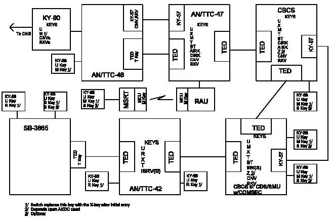 Figure III-1. Required Keys for a CBCS Network
______________________________________________________________
Figure III-1. Required Keys for a CBCS Network
______________________________________________________________
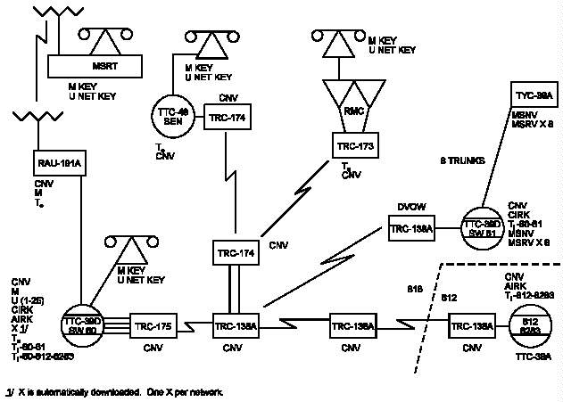 Figure III-2. Example CBCS Network
______________________________________________________________
c. Net Definition. Each switch will employ its X-keys,
or net keys, which are held by all of its directly connected
DSVTs and are used during the initial signaling phase.
U-keys are divided into 25 nets at each switch. Subscribers
are automatically assigned to a U net based on their user
profile. Nets U-24 and U-25 are reserved for S-key holders.
The maximum net size for the U-key is 250. To allow for
mobile subscribers to affiliate at any switch, the X- and
U-net keys must be common to a home area code.
d. LKG Usage. The LKGs contained in the HGF-85 or
HGF-87 COMSEC module are normally configured to operate on a
pooled basis. However, during the signaling phase and
conference calls (RED), the LKG will operate with the DSVT
in the link encryption mode. The LKG will encrypt and
decrypt signaling information in the X-key and will also
send the V-key using the DSVT assigned U-key. This same
V-key is also sent to the called DSVT using the U-key
assigned to that DSVT and another LKG. After completion of
the V-key distribution and dialing sequence by the LKGs, the
LKGs are switched back to the pooled mode, and the called
and calling DSVTs will synchronize in the V-key for
end-to-end operation using the per-call V-key. Upon
completion of the call, the called and calling party go
onhook and the V-key is erased from volatile memory. The
LKG will also operate in the link encryption mode when it
engages in a call with a secure DNVT. During the voice
mode, synchronization between DSVTs will be automatic using
the AUTO-RESYNC capability of the DSVT. This is the most
common example of LKG usage. LKGs are also used to transfer
X-key to DSVT subscribers whenever a DSVT affiliates with an
M- or R-key loaded in its X location and at the end of the
X-key cryptoperiod. Specific examples of other scenarios
are presented in paragraph 17.
e. Keys and Key Management. The primary means of key
distribution in the CBCS network is electronic bulk transfer
from AKDC to AKDC. These transfers are encrypted with the
BT key. (The BT key is always distributed manually.) Lists
of keys can be created and distributed using the Assign,
Transfer, and Activate Lists (ATL) and Assign Bulk Transfer
(ABT) screens of the NCS and LEN. Keys can be distributed
by manual operation of the AKDC. The AN/TTC-39A(V)1 is not
capable of bulk transfer.
3. Mobile Subscriber Equipment. MSE is the US Army's area
communications system for echelons corps and below. MSE
switches are CBCSs. There are three types of switches in
the MSE system: the AN/TTC-47 Node Center Switch (NCS), the
AN/TTC-46 Large Extension Node (LEN), and the AN/TTC-48 SEN.
The NCS and LEN function as a CPS. The system also contains
radio access units (RAUs), which work in conjunction with
NCSs to service mobile subscribers who have MSRTs. As a
result of CBCS modifications, MSE switches can now operate
at either 16 or 32 kbps. However, switches servicing RAUs
and MSRTs are restricted to 16 kbps. As an option, the LEN
and SEN can service CNR callers through a secure digital net
radio interface unit (SDNRIU). The SDNRIU is really a KY-90
and appears to the switch as a DSVT. SENs and RAUs must
have all keys trunking data duplicated to at least one
switch in addition to the servicing CPS, so the servicing
CPS can be bypassed if it fails. Two switches similar to
the MSE network switches, but used for different purposes,
are the AN/TTC-50 Force Entry Switch (FES) and the AN/TTC-51
Dismounted Extension Switch (DES). The FES is a CPS, while
the DES is CSS. See CJCSM 6231.02A for further information
about these switches.
a. COMSEC Equipment. Both the NCS and LEN contain one
KGX-93A AKDC. They also contain one HGF-96 transition unit
nest assembly (TUNA) and eight KG-112 dual LKGs. Both can
contain KG-94A or -194A TEDs; the NCS has 15, the LEN has 3.
No new KG-94As are being fielded. Existing KG-94As are
being replaced by KG-194As. The SEN performs no COMSEC
functions for its subscribers and contains only one TED.
The SEN and LEN can be configured with one KY-90. The RAU
uses the MO-3(C)/G mobile COMSEC unit (MCU) for encryption
of signaling between the RAU and each MSRT. The RAU
contains eight of these units; each MSRT contains one.
Traffic on these links is encrypted by DSVTs. The FES
contains one KGX-93A, one HGF-96, eight KG-112s, and up to
eight KG-194As. The DES contains one KG-194A. COMSEC
complements for MSE CPSs are shown in Table III-1.
b. Keys and Key Management. The primary means of key
distribution in the MSE network is electronic bulk transfer
from AKDC to AKDC. These transfers are encrypted with the
BT-key. (The BT-key is always distributed manually.) Lists
of keys can be created and distributed using the assign,
transfer, and activate lists (ATL) and assign bulk transfer
(ABT) screens of the NCS and LEN. Keys can also be
distributed by manual operation of the AKDC.
4. Unit Level Circuit Switches. The ULCSs are the
AN/TTC-42 and the SB-3865 (both are not CBCSs). The
AN/TTC-42 is a CPS, while the SB-3865 is a CSS. For more
information, see CJCSM 6231.02A.
a. COMSEC Equipment. The AN/TTC-42 contains 2 KGX-93
AKDCs, 2 HGF-93 TUNAs, and 16 KG-82 LKGs. It can also
contain up to six KG-94/194 TEDs, housed in two HGF-94
transition unit frame assemblies. The SB-3865 contains no
COMSEC equipment. It may use one KG-94A/194A TED, external
to the switch. Only Modem 001 may be secured by that TED.
The other two trunk groups must be secured at the
transmission facility. All three trunk groups should be
encrypted at the transmission facility, if possible.
b. Parent-Subordinate Relationships. The
alt-/co-parent relationship is a special relationship
established between two CPSs to provide alternate routing
for secure calls to and from a CSS network and to continue
providing COMSEC service to a CSS network in the event of a
catastrophic failure to the subordinate network's parent
switch. A co-parent is a CPS whose subordinate switch
network can be controlled by another CPS. An alt-parent is
a CPS capable of controlling the subordinate switch network
belonging to another CPS. Co- and alt-parent switches must
be directly connected. Home subordinate network is the term
used to refer to the CSS network of the co-parent switch.
Lateral subordinate network is the term used by the
alt-parent to refer to the CSS network of its co-parent.
SB-3865s are frequently deployed in networks with both alt-
and co-parent CPSs assigned. By holding keys for the
lateral CSS network, the alt-parent is able to provide
complete secure service for the CSS DSVTs, and, in the event
of a failure of the co-parent, resume any incomplete REKEYs
of the lateral network. The alt-parent must NOT initiate a
REKEY of the lateral network unless the alt-parent assigns
these switches as part of its home network. This process is
key management sensitive and is not recommended. The
alt-/co-parent relationship does not provide alternative
service for DSVTs or other terminals directly connected to a
CPS. It is only for selected CSSs which must have access to
a directly connected digital in-band trunk signaling (DIBTS)
link to the alt-parent. This route may be over other DIBTS
links within the lateral network; the route cannot be made
over or through a common channel interswitch signaling
(CCIS) link.
c. Keys and Key Management. The ULCSs use most of the
same keys as CBCSs. However, some keys have different
names. See Chapter II. AN/TTC-42s cannot perform bulk key
transfer in the same manner as CBCSs; however, electronic
key transfer between switches is possible. See
subparagraph 7d.
5. CBCS Database Considerations. Required CBCS database
parameters and worksheets are discussed in CJCSM 6231.02A.
This paragraph describes selected elements of the database
for secure subscribers.
a. Assign Digital Transmission Group (ADT). When a
digital transmission group (DTG) is assigned, the security
must also be designated. If security is required, a TED
must be installed and the proper classmark selected, which
is TED (0-15, 0 = NONE). The entry must be 0 if the DTG is
in repeater mode, supports a 4½ channel group to a remote
loop group multiplexer, or supports a multiplexed orderwire
group from the Orderwire Control Unit Type II. TEDs
available normal-through for specific DTGs, by switch type,
are shown in Table III-2. TEDs may be used for other DTGs,
but patching is required.
b. Assign Net Rekey (ANR). The ANR command identifies
a specific net or group of nets for a rekeying cycle, or
initiates a cold start for the SB-3865. The sequence of
entries for an SB-3865 cold start is G, 00, new net number.
______________________________________________________________
Table III-2. TEDS Available Normal-Through, by DTG
Switch Type DTGs Available
AN/TTC-39A(V)3 DTG 1 to TED 1
AN/TTC-39A(V)4 DTG 2 to TED 2
AN/TTC-39D DTG 3 to TED 3
CDS DTG 4 to TED 4
DTG 5 to TED 5
DTG 6 to TED 6
DTG 7 to TED 7
DTG 8 to TED 8
DTG 9 to TED 9
AN/TTC-39A(V)3 DTG 16 to TED 10
AN/TTC-39A(V)4 DTG 17 to TED 11
AN/TTC-39D DTG 18 to TED 12
DTG 19 to TED 13
DTG 20 to TED 14
DTG 21 to TED 15
AN/TSC-143 DTG 2 to TED 1
DTG 3 to TED 2
DTG 4 to TED 3
______________________________________________________________
AN/TTC-47 DTG 1 to TED 1
DTG 2 to TED 2
DTG 3 to TED 3
DTG 4 to TED 4
DTG 5 to TED 5
DTG 6 to TED 6
DTG 7 to TED 7
DTG 8 to TED 8
______________________________________________________________
AN/TTC-46 DTG 1 to TED 1
DTG 5 to TED 5
DTG 16 to TED 9
______________________________________________________________
c. Assign Variable Location (AVL). The AVL command
identifies the COMSEC ID for any optional keys used by the
CS. Required keys are assigned by executing the commands
AAL or APL. During initialization of the HGX-83 or KGX-
93/93A, one of them must be assigned to the online position,
which normally occurs on power-up, and the other must be
assigned to the standby position. However, if one of them
is not online, an ASSIGN ONLINE DIAGNOSTIC (AOD) command is
entered, which would be AOD-93, "HGX-83 SWITCHOVER UNIT #,
TYPE." Upon completion of this command, one of the AKDCs
status indications displays ONLINE. The other, if offline,
can be switched to the STANDBY position. This is done using
the AOD-93 command, "HGX-83 SWITCHOVER UNIT #, Type #3,"
where 3 indicates offline to standby. The AN/TTC-39A(V)1
requires all keys be entered by the AVL command. See CJCSM
6231.02A. A list of optional keys, with recommended storage
locations and other required information, is shown in
Table III-3.
_______________________________________________________________
Table III-3. Recommended Storage Locations for CBCS
Optional Keys
Recommended Storage
Location
Key HGX-83A KGX-93A Dir No/BS-LA Key Type Net No
_______________________________________________________________
AIRK 130-150 130-150 NYX AIRK N/A
SB-3865
Net 902-911 202-211 NNX(X) HN 2-11 1/
Rekey 151-159 151-159 NNX()X HRV 1-9 2/
Option 11
Net 902-911 202-211 NNX(X) SN 2-11 1/
Rekey 160-169 160-169 NNX(X) SRV 60-69 2/
MS
Net 902-911 202-211 XX-XX MSNV 2-11 1/
Rekey 170-198 170-198 XX-XX MSRV 70-98 2/
_______________________________________________________________
1/ Use last two digits of storage location as net number.
2/ Use last digit of storage location as net number.
_______________________________________________________________
d. Assign Transfer Lists (ATL). This command
identifies the COMSEC ID for a particular key or a range of
COMSEC IDs for a contiguous group of keys to be defined as a
list to be subsequently transferred to another switch. The
AN/TTC-39A(V)1 does not have this capability.
e. Assign Bulk Transfer (ABT). This command generates
or activates a key or list of keys, or transfers a key or
list of keys to another switch. The entry for
"authorization to accept bulk transfer" must be set to Y in
the receiving switch in order to accept bulk transfer. The
AN/TTC-39A(V)1 does not have this capability. Neither does
the AN/TTC-42.
f. Duplication and Bypass. CBCSs use a series of
commands (assign bypass and duplication (ABD), assign bypass
reception (ABR), and assign local duplication (ALD)) to
accommodate SEN and RAU subscribers and designated essential
users in the event of switch failure. There is no longer a
specific set of commands required to accommodate essential
users, nor is there a set of keys specifically designated
for essential users. See CJCSM 6231.02A for more
information about duplication and bypass.
g. Security Classmarks. Security classmarks are part
of each individual subscriber's profile and are assigned
automatically using the APL, AAL, or APF commands. The four
classmarks are: P = Preferred, R = Required, N = Nonsecure,
and E = End-To-End Encryption Required.
6. AN/TTC-42 Database Construction. COMSEC functions are
performed using a series of menu-based index (IDX)
procedures. These procedures are divided into three
categories: key assignment, rekey management, and
transfer/purge control. Worksheets to aid in performing
these functions are contained in CJCSM 6231.02A.
a. Key Assignment. This series of procedures enables
the operator to perform net key assignments, local DSVT
assignments, ISRV assignments, subordinate switch
assignments, and external key assignments, and to display
AKDC status. The information required to make these
assignments is basically the same as for the AN/TTC-39();
however, the terminology and information entry order are
different.
b. Rekey Management. These procedures allow the
operator to rekey the home subnetwork (REKEY NET), a
particular switch (REKEY SWITCH), or the lateral subnetwork
(REKEY LAT NET). They also allow the operator to change or
display rekeying status.
c. Transfer/Purge Control. This series of procedures
allows net, rekey, and CSS keys to be purged or transferred
to the alt-parent.
7. Co-Parent and Alt-Parent Procedures for ULCS. The co-
and alt-parent must be directly connected (no intermediate
switch).
a. At the Alt-Parent. The operator defines the
alt-parent, loads the UISRV in AKDC UVS location 008, and
enters the co-parent's home CSS network as lateral CSSs.
The alt-parent must have a direct DIBTS route to the lateral
network. (For proper network routing, this route MUST be
the primary route from the alt-parent to the lateral
network.)
b. At the Co-Parent. The operator defines the
alt-parent and loads the UISRV in AKDC UVS location 007.
(This UISRV is no different than any other UISRV, except
that it is also used to encrypt the transfer of the Reentry,
Net, and U-keys assigned to the home CSS of the alt-parent.)
The operator performs Command 11 at the AKDC to transfer
Reentry and U-keys to the lateral switch. The switch will
not default if this is not done. The operator then rekeys
home CSS switches. The switch defaults to require these net
keys be transferred to the alt-parent before the REKEY
function is initiated. Upon successful transfer of keys,
the alt- and co-parent relationship is established.
c. At the CSS Network. The operators define the
co-parent and alt-parent switches. The link from the
lateral network to the alt-parent must be the PRIMARY route
from each lateral switch to the alt-parent and to that
portion of the network which is accessed through that
switch. If the primary route is selected through the
co-parent, alt-routing will not occur if the link between
the alt- and co-parent is "out of service" or "busy."
d. Key Transfer. Although the AN/TTC-42 does not
perform a "bulk" transfer, it can be used to transfer keys
between switches. To perform this function, the
TRANSMITTING switch must define the RECEIVING switch as an
alt-parent, while the RECEIVING switch defines the
TRANSMITTING switch as a co-parent. A "dummy" CSS is then
entered in each switch as either a home or lateral switch,
as appropriate. Each switch must then load the KEK as the
UISRV in either location 007 or 008. A manual "transfer
variable" routine is then initiated by the co-parent
operator, who then may transfer the key(s) to the
alt-parent. Although appearing cumbersome, this is an easy
method to transfer (OTAT) a large number of keys through the
network. This procedure must be done between directly
connected CPSs. Using this method, it is possible with one
common, two party key in the network, for one switch to
generate certain keys and initialize the network without
dependence upon keytape.
8. Keys and Key Management. Keys used in circuit switch
applications are discussed in Chapter II. All keys in
electronic form will be accounted for in a log. The log is
CONFIDENTIAL when filled in.
9. Key Assignments Within the HUS. All keys that are
required for CBCS operation have preassigned HUS locations.
These locations are shown in Table III-4. Additional
(optional) keys are assigned using the AVL command.
Recommended key locations are in Table III-3. After keys
have been assigned to the HUS, use Command 57 to transfer
variables from the HUS/COMSEC ID to the AKDC Fill Buffer and
then to a fill device. Command 57 is used to load the fill
devices for distribution of variables to local subscribers.
Remote subscribers normally receive variables via pre-
positioned tape, and these subscriber terminals must be
loaded using the KOI-18 tape reader. HUS locations used by
the Marine Corps in the AN/TTC-42 are shown in Table III-5.
10. Load TED to TED (Trunking). When assigning a digital
transmission group, the TED must be assigned if traffic flow
security is needed for a particular deployment. Therefore,
if traffic flow security is required between two AN/TTC-39s,
the TEDs must be assigned using the ADT Command--Assign
Digital Transmission Group--which is TED (0-15, 0 = NONE).
Before activating the TEDS, they must be internally strapped
for proper operation (see Apendix G). TEDS are also used
for traffic encryption in some applications.
11. Tactical-Strategic Interface. Interface to the Defense
Red Switch Network or other strategic secure network can be
done in two ways, though the specific type of secure switch
or availability of other required equipment may force the
use of one method instead of the other. One method is
through a DSVT (or equivalent) at the strategic end. This
DSVT is treated as a long loop off the AN/TTC-39(). (See
Figure III-3.) Another example of this connectivity is
shown in Figure III-4. The other method involves
establishing interswitch trunks using multiple rate voice
cards (MRVCs) at both ends. This is a nonstandard con-
figuration, using KG-84() family equipment at both ends.
Typical connectivity for this method is shown in
Figure III-5. Required keys are the appropriate U- and
X-keys. Hard-copy key material is required to support these
interfaces. Technical information about establishing these
interfaces and others can be found in CJCSM 6231.02A.
______________________________________________________________
Table III-4. CBCS Storage Locations for Preassigned Keys
_____________________________________________________________
HGX-83 HUS FUNCTION KGX-93 HUS
LOCATIONS LOCATIONS
_______________ _______________
A B A B
_____________________________________________________________
0 223 RESERVED 0 256
1 224 CIRIK 1 257
2 225 COMMON BT 2 258
3 226 U NET 1 3 259
4 227 NET 2 4 260
5 228 NET 3 5 261
6 229 NET 4 6 262
7 230 NET 5 7 263
8 231 NET 6 8 264
9 232 NET 7 9 265
10 233 NET 8 10 266
11 234 NET 9 11 267
12 235 NET 10 12 268
13 236 NET 11 13 269
14 237 NET 12 14 270
15 238 NET 13 15 271
16 239 NET 14 16 272
17 240 NET 15 17 273
18 241 NET 16 18 274
19 242 NET 17 19 275
20 243 NET 18 20 276
21 244 NET 19 21 277
22 245 NET 20 22 278
23 246 NET 21 23 279
24 247 NET 22 24 280
25 248 NET 23 25 281
26 249 NET 24 26 282
27 250 NET 25 27 283
28 251 RKV 28 284
29 252 CNV 29 285
30 253 TI 30 286
31-96 254-319 AVAILABLE 31-96 287-35
97 320 RKV 97 353
98 321 RKV 98 354
99 322 RKV 99 355
100 323 RKV 100 356
101 324 T 101 357
102 325 T 102 358
103 326 T 103 359
104 327 T 104 360
105 328 T 105 361
106 329 T 106 362
107 330 T 107 363
108 331 T 108 364
109 332 T 109 365
110 333 T 110 366
111 334 T 111 367
112 335 T 112 368
113 336 T 113 369
114 337 T 114 370
115 338 T 115 371
116 339 T 116 372
117 340 T 117 373
118 341 T 118 374
119 342 T 119 375
120 343 T 120 376
121 344 T 121 377
122 345 T 122 378
123 346 T 123 379
124 347 T 124 380
125 348 T 125 381
126-222 349-445 AVAILABLE 126-222 382-478
880 912 M 224 480
881 913 NET 2(A) X NET 27(B) 225 481
882-911 914-943 AVAILABLE 226-255 482-511
446-879 944-1007 AVAILABLE
_____________________________________________________________
________________________________________________________________
Table III-5. AN/TTC-42 HUS Allocations
________________________________________________________________
Location Key Type Remarks
________________________________________________________________
000 Reserved for switch use
001 CISRV Location must be marked "valid"
002 ISRV Formerly reserved for DAMA ISRV,
not used
003-006 AISRV
007 UISRV Of alt-parent, at co-parent
008 UISRV Of co-parent, at alt-parent
009-070 UISRV
071-100 Spare Extra-switch, not used by switch
software
101-220 U Directly connected subscribers
221 U Post-nuclear
222-223 Reserved for AKDC diagnostics
224-253 X Home nets
254 R May be ICP long local key
255 X post-nuclear
256-300 Spare Extra-switch
301-348 U CSS subscribers
349-400 Spare Extra-switch
401-448 U Lateral subnetwork
449-476 Spare Extra-switch
477 CISRV Lateral switch
478-479 Reserved for AKDC diagnostics
480-509 X Lateral subnetwork
510 R Lateral subnetwork
511 CISRV Lateral switch
________________________________________________________________
Figure III-2. Example CBCS Network
______________________________________________________________
c. Net Definition. Each switch will employ its X-keys,
or net keys, which are held by all of its directly connected
DSVTs and are used during the initial signaling phase.
U-keys are divided into 25 nets at each switch. Subscribers
are automatically assigned to a U net based on their user
profile. Nets U-24 and U-25 are reserved for S-key holders.
The maximum net size for the U-key is 250. To allow for
mobile subscribers to affiliate at any switch, the X- and
U-net keys must be common to a home area code.
d. LKG Usage. The LKGs contained in the HGF-85 or
HGF-87 COMSEC module are normally configured to operate on a
pooled basis. However, during the signaling phase and
conference calls (RED), the LKG will operate with the DSVT
in the link encryption mode. The LKG will encrypt and
decrypt signaling information in the X-key and will also
send the V-key using the DSVT assigned U-key. This same
V-key is also sent to the called DSVT using the U-key
assigned to that DSVT and another LKG. After completion of
the V-key distribution and dialing sequence by the LKGs, the
LKGs are switched back to the pooled mode, and the called
and calling DSVTs will synchronize in the V-key for
end-to-end operation using the per-call V-key. Upon
completion of the call, the called and calling party go
onhook and the V-key is erased from volatile memory. The
LKG will also operate in the link encryption mode when it
engages in a call with a secure DNVT. During the voice
mode, synchronization between DSVTs will be automatic using
the AUTO-RESYNC capability of the DSVT. This is the most
common example of LKG usage. LKGs are also used to transfer
X-key to DSVT subscribers whenever a DSVT affiliates with an
M- or R-key loaded in its X location and at the end of the
X-key cryptoperiod. Specific examples of other scenarios
are presented in paragraph 17.
e. Keys and Key Management. The primary means of key
distribution in the CBCS network is electronic bulk transfer
from AKDC to AKDC. These transfers are encrypted with the
BT key. (The BT key is always distributed manually.) Lists
of keys can be created and distributed using the Assign,
Transfer, and Activate Lists (ATL) and Assign Bulk Transfer
(ABT) screens of the NCS and LEN. Keys can be distributed
by manual operation of the AKDC. The AN/TTC-39A(V)1 is not
capable of bulk transfer.
3. Mobile Subscriber Equipment. MSE is the US Army's area
communications system for echelons corps and below. MSE
switches are CBCSs. There are three types of switches in
the MSE system: the AN/TTC-47 Node Center Switch (NCS), the
AN/TTC-46 Large Extension Node (LEN), and the AN/TTC-48 SEN.
The NCS and LEN function as a CPS. The system also contains
radio access units (RAUs), which work in conjunction with
NCSs to service mobile subscribers who have MSRTs. As a
result of CBCS modifications, MSE switches can now operate
at either 16 or 32 kbps. However, switches servicing RAUs
and MSRTs are restricted to 16 kbps. As an option, the LEN
and SEN can service CNR callers through a secure digital net
radio interface unit (SDNRIU). The SDNRIU is really a KY-90
and appears to the switch as a DSVT. SENs and RAUs must
have all keys trunking data duplicated to at least one
switch in addition to the servicing CPS, so the servicing
CPS can be bypassed if it fails. Two switches similar to
the MSE network switches, but used for different purposes,
are the AN/TTC-50 Force Entry Switch (FES) and the AN/TTC-51
Dismounted Extension Switch (DES). The FES is a CPS, while
the DES is CSS. See CJCSM 6231.02A for further information
about these switches.
a. COMSEC Equipment. Both the NCS and LEN contain one
KGX-93A AKDC. They also contain one HGF-96 transition unit
nest assembly (TUNA) and eight KG-112 dual LKGs. Both can
contain KG-94A or -194A TEDs; the NCS has 15, the LEN has 3.
No new KG-94As are being fielded. Existing KG-94As are
being replaced by KG-194As. The SEN performs no COMSEC
functions for its subscribers and contains only one TED.
The SEN and LEN can be configured with one KY-90. The RAU
uses the MO-3(C)/G mobile COMSEC unit (MCU) for encryption
of signaling between the RAU and each MSRT. The RAU
contains eight of these units; each MSRT contains one.
Traffic on these links is encrypted by DSVTs. The FES
contains one KGX-93A, one HGF-96, eight KG-112s, and up to
eight KG-194As. The DES contains one KG-194A. COMSEC
complements for MSE CPSs are shown in Table III-1.
b. Keys and Key Management. The primary means of key
distribution in the MSE network is electronic bulk transfer
from AKDC to AKDC. These transfers are encrypted with the
BT-key. (The BT-key is always distributed manually.) Lists
of keys can be created and distributed using the assign,
transfer, and activate lists (ATL) and assign bulk transfer
(ABT) screens of the NCS and LEN. Keys can also be
distributed by manual operation of the AKDC.
4. Unit Level Circuit Switches. The ULCSs are the
AN/TTC-42 and the SB-3865 (both are not CBCSs). The
AN/TTC-42 is a CPS, while the SB-3865 is a CSS. For more
information, see CJCSM 6231.02A.
a. COMSEC Equipment. The AN/TTC-42 contains 2 KGX-93
AKDCs, 2 HGF-93 TUNAs, and 16 KG-82 LKGs. It can also
contain up to six KG-94/194 TEDs, housed in two HGF-94
transition unit frame assemblies. The SB-3865 contains no
COMSEC equipment. It may use one KG-94A/194A TED, external
to the switch. Only Modem 001 may be secured by that TED.
The other two trunk groups must be secured at the
transmission facility. All three trunk groups should be
encrypted at the transmission facility, if possible.
b. Parent-Subordinate Relationships. The
alt-/co-parent relationship is a special relationship
established between two CPSs to provide alternate routing
for secure calls to and from a CSS network and to continue
providing COMSEC service to a CSS network in the event of a
catastrophic failure to the subordinate network's parent
switch. A co-parent is a CPS whose subordinate switch
network can be controlled by another CPS. An alt-parent is
a CPS capable of controlling the subordinate switch network
belonging to another CPS. Co- and alt-parent switches must
be directly connected. Home subordinate network is the term
used to refer to the CSS network of the co-parent switch.
Lateral subordinate network is the term used by the
alt-parent to refer to the CSS network of its co-parent.
SB-3865s are frequently deployed in networks with both alt-
and co-parent CPSs assigned. By holding keys for the
lateral CSS network, the alt-parent is able to provide
complete secure service for the CSS DSVTs, and, in the event
of a failure of the co-parent, resume any incomplete REKEYs
of the lateral network. The alt-parent must NOT initiate a
REKEY of the lateral network unless the alt-parent assigns
these switches as part of its home network. This process is
key management sensitive and is not recommended. The
alt-/co-parent relationship does not provide alternative
service for DSVTs or other terminals directly connected to a
CPS. It is only for selected CSSs which must have access to
a directly connected digital in-band trunk signaling (DIBTS)
link to the alt-parent. This route may be over other DIBTS
links within the lateral network; the route cannot be made
over or through a common channel interswitch signaling
(CCIS) link.
c. Keys and Key Management. The ULCSs use most of the
same keys as CBCSs. However, some keys have different
names. See Chapter II. AN/TTC-42s cannot perform bulk key
transfer in the same manner as CBCSs; however, electronic
key transfer between switches is possible. See
subparagraph 7d.
5. CBCS Database Considerations. Required CBCS database
parameters and worksheets are discussed in CJCSM 6231.02A.
This paragraph describes selected elements of the database
for secure subscribers.
a. Assign Digital Transmission Group (ADT). When a
digital transmission group (DTG) is assigned, the security
must also be designated. If security is required, a TED
must be installed and the proper classmark selected, which
is TED (0-15, 0 = NONE). The entry must be 0 if the DTG is
in repeater mode, supports a 4½ channel group to a remote
loop group multiplexer, or supports a multiplexed orderwire
group from the Orderwire Control Unit Type II. TEDs
available normal-through for specific DTGs, by switch type,
are shown in Table III-2. TEDs may be used for other DTGs,
but patching is required.
b. Assign Net Rekey (ANR). The ANR command identifies
a specific net or group of nets for a rekeying cycle, or
initiates a cold start for the SB-3865. The sequence of
entries for an SB-3865 cold start is G, 00, new net number.
______________________________________________________________
Table III-2. TEDS Available Normal-Through, by DTG
Switch Type DTGs Available
AN/TTC-39A(V)3 DTG 1 to TED 1
AN/TTC-39A(V)4 DTG 2 to TED 2
AN/TTC-39D DTG 3 to TED 3
CDS DTG 4 to TED 4
DTG 5 to TED 5
DTG 6 to TED 6
DTG 7 to TED 7
DTG 8 to TED 8
DTG 9 to TED 9
AN/TTC-39A(V)3 DTG 16 to TED 10
AN/TTC-39A(V)4 DTG 17 to TED 11
AN/TTC-39D DTG 18 to TED 12
DTG 19 to TED 13
DTG 20 to TED 14
DTG 21 to TED 15
AN/TSC-143 DTG 2 to TED 1
DTG 3 to TED 2
DTG 4 to TED 3
______________________________________________________________
AN/TTC-47 DTG 1 to TED 1
DTG 2 to TED 2
DTG 3 to TED 3
DTG 4 to TED 4
DTG 5 to TED 5
DTG 6 to TED 6
DTG 7 to TED 7
DTG 8 to TED 8
______________________________________________________________
AN/TTC-46 DTG 1 to TED 1
DTG 5 to TED 5
DTG 16 to TED 9
______________________________________________________________
c. Assign Variable Location (AVL). The AVL command
identifies the COMSEC ID for any optional keys used by the
CS. Required keys are assigned by executing the commands
AAL or APL. During initialization of the HGX-83 or KGX-
93/93A, one of them must be assigned to the online position,
which normally occurs on power-up, and the other must be
assigned to the standby position. However, if one of them
is not online, an ASSIGN ONLINE DIAGNOSTIC (AOD) command is
entered, which would be AOD-93, "HGX-83 SWITCHOVER UNIT #,
TYPE." Upon completion of this command, one of the AKDCs
status indications displays ONLINE. The other, if offline,
can be switched to the STANDBY position. This is done using
the AOD-93 command, "HGX-83 SWITCHOVER UNIT #, Type #3,"
where 3 indicates offline to standby. The AN/TTC-39A(V)1
requires all keys be entered by the AVL command. See CJCSM
6231.02A. A list of optional keys, with recommended storage
locations and other required information, is shown in
Table III-3.
_______________________________________________________________
Table III-3. Recommended Storage Locations for CBCS
Optional Keys
Recommended Storage
Location
Key HGX-83A KGX-93A Dir No/BS-LA Key Type Net No
_______________________________________________________________
AIRK 130-150 130-150 NYX AIRK N/A
SB-3865
Net 902-911 202-211 NNX(X) HN 2-11 1/
Rekey 151-159 151-159 NNX()X HRV 1-9 2/
Option 11
Net 902-911 202-211 NNX(X) SN 2-11 1/
Rekey 160-169 160-169 NNX(X) SRV 60-69 2/
MS
Net 902-911 202-211 XX-XX MSNV 2-11 1/
Rekey 170-198 170-198 XX-XX MSRV 70-98 2/
_______________________________________________________________
1/ Use last two digits of storage location as net number.
2/ Use last digit of storage location as net number.
_______________________________________________________________
d. Assign Transfer Lists (ATL). This command
identifies the COMSEC ID for a particular key or a range of
COMSEC IDs for a contiguous group of keys to be defined as a
list to be subsequently transferred to another switch. The
AN/TTC-39A(V)1 does not have this capability.
e. Assign Bulk Transfer (ABT). This command generates
or activates a key or list of keys, or transfers a key or
list of keys to another switch. The entry for
"authorization to accept bulk transfer" must be set to Y in
the receiving switch in order to accept bulk transfer. The
AN/TTC-39A(V)1 does not have this capability. Neither does
the AN/TTC-42.
f. Duplication and Bypass. CBCSs use a series of
commands (assign bypass and duplication (ABD), assign bypass
reception (ABR), and assign local duplication (ALD)) to
accommodate SEN and RAU subscribers and designated essential
users in the event of switch failure. There is no longer a
specific set of commands required to accommodate essential
users, nor is there a set of keys specifically designated
for essential users. See CJCSM 6231.02A for more
information about duplication and bypass.
g. Security Classmarks. Security classmarks are part
of each individual subscriber's profile and are assigned
automatically using the APL, AAL, or APF commands. The four
classmarks are: P = Preferred, R = Required, N = Nonsecure,
and E = End-To-End Encryption Required.
6. AN/TTC-42 Database Construction. COMSEC functions are
performed using a series of menu-based index (IDX)
procedures. These procedures are divided into three
categories: key assignment, rekey management, and
transfer/purge control. Worksheets to aid in performing
these functions are contained in CJCSM 6231.02A.
a. Key Assignment. This series of procedures enables
the operator to perform net key assignments, local DSVT
assignments, ISRV assignments, subordinate switch
assignments, and external key assignments, and to display
AKDC status. The information required to make these
assignments is basically the same as for the AN/TTC-39();
however, the terminology and information entry order are
different.
b. Rekey Management. These procedures allow the
operator to rekey the home subnetwork (REKEY NET), a
particular switch (REKEY SWITCH), or the lateral subnetwork
(REKEY LAT NET). They also allow the operator to change or
display rekeying status.
c. Transfer/Purge Control. This series of procedures
allows net, rekey, and CSS keys to be purged or transferred
to the alt-parent.
7. Co-Parent and Alt-Parent Procedures for ULCS. The co-
and alt-parent must be directly connected (no intermediate
switch).
a. At the Alt-Parent. The operator defines the
alt-parent, loads the UISRV in AKDC UVS location 008, and
enters the co-parent's home CSS network as lateral CSSs.
The alt-parent must have a direct DIBTS route to the lateral
network. (For proper network routing, this route MUST be
the primary route from the alt-parent to the lateral
network.)
b. At the Co-Parent. The operator defines the
alt-parent and loads the UISRV in AKDC UVS location 007.
(This UISRV is no different than any other UISRV, except
that it is also used to encrypt the transfer of the Reentry,
Net, and U-keys assigned to the home CSS of the alt-parent.)
The operator performs Command 11 at the AKDC to transfer
Reentry and U-keys to the lateral switch. The switch will
not default if this is not done. The operator then rekeys
home CSS switches. The switch defaults to require these net
keys be transferred to the alt-parent before the REKEY
function is initiated. Upon successful transfer of keys,
the alt- and co-parent relationship is established.
c. At the CSS Network. The operators define the
co-parent and alt-parent switches. The link from the
lateral network to the alt-parent must be the PRIMARY route
from each lateral switch to the alt-parent and to that
portion of the network which is accessed through that
switch. If the primary route is selected through the
co-parent, alt-routing will not occur if the link between
the alt- and co-parent is "out of service" or "busy."
d. Key Transfer. Although the AN/TTC-42 does not
perform a "bulk" transfer, it can be used to transfer keys
between switches. To perform this function, the
TRANSMITTING switch must define the RECEIVING switch as an
alt-parent, while the RECEIVING switch defines the
TRANSMITTING switch as a co-parent. A "dummy" CSS is then
entered in each switch as either a home or lateral switch,
as appropriate. Each switch must then load the KEK as the
UISRV in either location 007 or 008. A manual "transfer
variable" routine is then initiated by the co-parent
operator, who then may transfer the key(s) to the
alt-parent. Although appearing cumbersome, this is an easy
method to transfer (OTAT) a large number of keys through the
network. This procedure must be done between directly
connected CPSs. Using this method, it is possible with one
common, two party key in the network, for one switch to
generate certain keys and initialize the network without
dependence upon keytape.
8. Keys and Key Management. Keys used in circuit switch
applications are discussed in Chapter II. All keys in
electronic form will be accounted for in a log. The log is
CONFIDENTIAL when filled in.
9. Key Assignments Within the HUS. All keys that are
required for CBCS operation have preassigned HUS locations.
These locations are shown in Table III-4. Additional
(optional) keys are assigned using the AVL command.
Recommended key locations are in Table III-3. After keys
have been assigned to the HUS, use Command 57 to transfer
variables from the HUS/COMSEC ID to the AKDC Fill Buffer and
then to a fill device. Command 57 is used to load the fill
devices for distribution of variables to local subscribers.
Remote subscribers normally receive variables via pre-
positioned tape, and these subscriber terminals must be
loaded using the KOI-18 tape reader. HUS locations used by
the Marine Corps in the AN/TTC-42 are shown in Table III-5.
10. Load TED to TED (Trunking). When assigning a digital
transmission group, the TED must be assigned if traffic flow
security is needed for a particular deployment. Therefore,
if traffic flow security is required between two AN/TTC-39s,
the TEDs must be assigned using the ADT Command--Assign
Digital Transmission Group--which is TED (0-15, 0 = NONE).
Before activating the TEDS, they must be internally strapped
for proper operation (see Apendix G). TEDS are also used
for traffic encryption in some applications.
11. Tactical-Strategic Interface. Interface to the Defense
Red Switch Network or other strategic secure network can be
done in two ways, though the specific type of secure switch
or availability of other required equipment may force the
use of one method instead of the other. One method is
through a DSVT (or equivalent) at the strategic end. This
DSVT is treated as a long loop off the AN/TTC-39(). (See
Figure III-3.) Another example of this connectivity is
shown in Figure III-4. The other method involves
establishing interswitch trunks using multiple rate voice
cards (MRVCs) at both ends. This is a nonstandard con-
figuration, using KG-84() family equipment at both ends.
Typical connectivity for this method is shown in
Figure III-5. Required keys are the appropriate U- and
X-keys. Hard-copy key material is required to support these
interfaces. Technical information about establishing these
interfaces and others can be found in CJCSM 6231.02A.
______________________________________________________________
Table III-4. CBCS Storage Locations for Preassigned Keys
_____________________________________________________________
HGX-83 HUS FUNCTION KGX-93 HUS
LOCATIONS LOCATIONS
_______________ _______________
A B A B
_____________________________________________________________
0 223 RESERVED 0 256
1 224 CIRIK 1 257
2 225 COMMON BT 2 258
3 226 U NET 1 3 259
4 227 NET 2 4 260
5 228 NET 3 5 261
6 229 NET 4 6 262
7 230 NET 5 7 263
8 231 NET 6 8 264
9 232 NET 7 9 265
10 233 NET 8 10 266
11 234 NET 9 11 267
12 235 NET 10 12 268
13 236 NET 11 13 269
14 237 NET 12 14 270
15 238 NET 13 15 271
16 239 NET 14 16 272
17 240 NET 15 17 273
18 241 NET 16 18 274
19 242 NET 17 19 275
20 243 NET 18 20 276
21 244 NET 19 21 277
22 245 NET 20 22 278
23 246 NET 21 23 279
24 247 NET 22 24 280
25 248 NET 23 25 281
26 249 NET 24 26 282
27 250 NET 25 27 283
28 251 RKV 28 284
29 252 CNV 29 285
30 253 TI 30 286
31-96 254-319 AVAILABLE 31-96 287-35
97 320 RKV 97 353
98 321 RKV 98 354
99 322 RKV 99 355
100 323 RKV 100 356
101 324 T 101 357
102 325 T 102 358
103 326 T 103 359
104 327 T 104 360
105 328 T 105 361
106 329 T 106 362
107 330 T 107 363
108 331 T 108 364
109 332 T 109 365
110 333 T 110 366
111 334 T 111 367
112 335 T 112 368
113 336 T 113 369
114 337 T 114 370
115 338 T 115 371
116 339 T 116 372
117 340 T 117 373
118 341 T 118 374
119 342 T 119 375
120 343 T 120 376
121 344 T 121 377
122 345 T 122 378
123 346 T 123 379
124 347 T 124 380
125 348 T 125 381
126-222 349-445 AVAILABLE 126-222 382-478
880 912 M 224 480
881 913 NET 2(A) X NET 27(B) 225 481
882-911 914-943 AVAILABLE 226-255 482-511
446-879 944-1007 AVAILABLE
_____________________________________________________________
________________________________________________________________
Table III-5. AN/TTC-42 HUS Allocations
________________________________________________________________
Location Key Type Remarks
________________________________________________________________
000 Reserved for switch use
001 CISRV Location must be marked "valid"
002 ISRV Formerly reserved for DAMA ISRV,
not used
003-006 AISRV
007 UISRV Of alt-parent, at co-parent
008 UISRV Of co-parent, at alt-parent
009-070 UISRV
071-100 Spare Extra-switch, not used by switch
software
101-220 U Directly connected subscribers
221 U Post-nuclear
222-223 Reserved for AKDC diagnostics
224-253 X Home nets
254 R May be ICP long local key
255 X post-nuclear
256-300 Spare Extra-switch
301-348 U CSS subscribers
349-400 Spare Extra-switch
401-448 U Lateral subnetwork
449-476 Spare Extra-switch
477 CISRV Lateral switch
478-479 Reserved for AKDC diagnostics
480-509 X Lateral subnetwork
510 R Lateral subnetwork
511 CISRV Lateral switch
________________________________________________________________
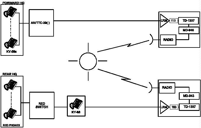 Figure III-3. Typical Red Switch Connectivity
________________________________________________________________
Figure III-3. Typical Red Switch Connectivity
________________________________________________________________
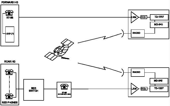 Figure III-4. Possible Red Switch Connectivity
________________________________________________________________
Figure III-4. Possible Red Switch Connectivity
________________________________________________________________
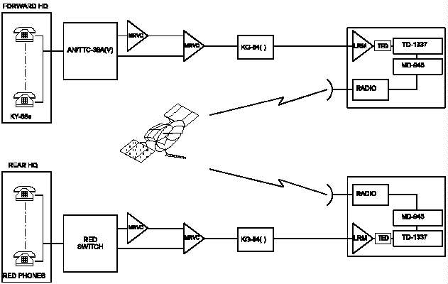 Figure III-5. Example Red Switch Interswitch Trunk Connectivity
________________________________________________________________
12. Protected Distribution Systems and Approved Loops.
CBCSs permit switches and their subscribers to operate in a
PDS, using different handling rules for secure calls than
would be used for unprotected distribution systems. The
switch is classmarked for PDS operation using the PDS=Y/N
entry on the assign switch initialization (ASI) screen.
PDS=Y allows SECRET-high traffic to operate in areas of the
network without encryption. DNVT subscribers classmarked
SP, when affiliated with a PDS=Y switch, may complete secure
calls to any DSVT subscribers in the network, any DNVT
subscribers that are classmarked SP at a PDS=Y switch, or
any SR subscribers. The Army operates its switches PDS=Y,
while the other Services and JCSE operate PDS=N. Switches
classmarked PDS=N may use approved loops for DNVT and analog
subscribers, though this is seldom done. The "approved
loop" must meet the requirements specified for a PDS in
NSTISSI 7003 and NACSIM 5203. The DNVT (or other telephones
so classmarked) can talk only to a secure subscriber. When
approved loops are implemented, the secure call privilege on
those loops must be R = Required. For the DSVT, the secure
call privilege can be R or P = Preferred. When the R
classmark is used, a secure path must be available to
complete the call. Therefore, it is suggested that the
DSVTs use the secure call privilege P. Army DNVT
subscribers classmarked SP may affiliate at a PDS=N switch,
but will be downgraded to NS, and NSWT will be played
throughout all calls. Figures III-6, III-7, and III-8
illustrate different call combinations in a mixed (PDS= Y or
N) network. Table III-6 lists allowable calls in CBCS
networks. See NSTISSI 7003 for more information about PDS
requirements.
________________________________________________________________
Figure III-5. Example Red Switch Interswitch Trunk Connectivity
________________________________________________________________
12. Protected Distribution Systems and Approved Loops.
CBCSs permit switches and their subscribers to operate in a
PDS, using different handling rules for secure calls than
would be used for unprotected distribution systems. The
switch is classmarked for PDS operation using the PDS=Y/N
entry on the assign switch initialization (ASI) screen.
PDS=Y allows SECRET-high traffic to operate in areas of the
network without encryption. DNVT subscribers classmarked
SP, when affiliated with a PDS=Y switch, may complete secure
calls to any DSVT subscribers in the network, any DNVT
subscribers that are classmarked SP at a PDS=Y switch, or
any SR subscribers. The Army operates its switches PDS=Y,
while the other Services and JCSE operate PDS=N. Switches
classmarked PDS=N may use approved loops for DNVT and analog
subscribers, though this is seldom done. The "approved
loop" must meet the requirements specified for a PDS in
NSTISSI 7003 and NACSIM 5203. The DNVT (or other telephones
so classmarked) can talk only to a secure subscriber. When
approved loops are implemented, the secure call privilege on
those loops must be R = Required. For the DSVT, the secure
call privilege can be R or P = Preferred. When the R
classmark is used, a secure path must be available to
complete the call. Therefore, it is suggested that the
DSVTs use the secure call privilege P. Army DNVT
subscribers classmarked SP may affiliate at a PDS=N switch,
but will be downgraded to NS, and NSWT will be played
throughout all calls. Figures III-6, III-7, and III-8
illustrate different call combinations in a mixed (PDS= Y or
N) network. Table III-6 lists allowable calls in CBCS
networks. See NSTISSI 7003 for more information about PDS
requirements.
________________________________________________________________
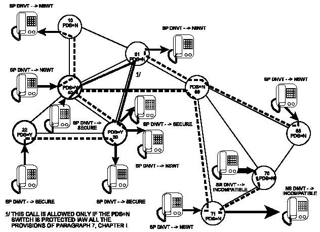 Figure III-6. PDS Call Combinations (1 of 3)
________________________________________________________________
Figure III-6. PDS Call Combinations (1 of 3)
________________________________________________________________
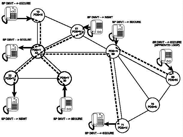 Figure III-7. PDS Call Combinations (2 of 3)
________________________________________________________________
Figure III-7. PDS Call Combinations (2 of 3)
________________________________________________________________
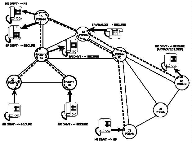 Figure III-8. PDS Call Combinations (3 of 3)
________________________________________________________________
__________________________________________________________________
Table III-6. CBCS Allowable Calls
__________________________________________________________________
Calling Called
Subscriber Subscriber
Approved DNVT or
Loop Analog DNVT DSVT DSVT DSVT
R NS P 1/ P R E
__________________________________________________________________
Approved Yes No Yes Yes Yes No
Loop
R
DNVT or Analog No Yes Yes Yes No No
NS NSWT 2/ NSWT 2/
DNVT Yes Yes Yes Yes Yes 4/
P 1/ NSWT 2/ 3/
DNVT Yes No Yes Yes Yes No
R
DSVT Yes Yes Yes Yes Yes No
P NSWT 2/
DSVT Yes No Yes Yes Yes Yes
R
DSVT No No 4/ Yes Yes Yes
E
_________
1/ At CBCS marked PDS=Y. At PDS=N switch, reverts to NS and always
receives NSWT. Calls that originate and terminate at PDS=Y switches
but tandem through PDS=N switches are allowable as long as the PDS=N
switches are protected IAW all of the provisions of paragraph 7.
Chapter I. If those switches cannot be protected as specified,
routing restrictions must be imposed to prevent those calls from
occurring.
2/ NSWT is only applied at the P terminal.
3/ NSWT may be provided to both terminals if the connecting path
contains nonsecure trunks.
4/ No for voice calls, Yes for data-initiated calls. Applies if DNVT
at PDS=Y and DSVT is at PDS=N, for traffic at SECRET level or below.
Legend: Secure Call Privilege
R = Required
NS = Nonsecure
P = Preferred
E = End-to-End
NSWT = Nonecure Warning Tone
__________________________________________________________________
13. Dial-Up Message Switch Connectivity. See
CJCSM 6231.03A for database entries for this service.
a. CBCSs. AN/UGC-144s can be configured for message
switch access through an AN/TTC-39(). The AN/UGC-144 is
used in conjunction with a DSVT in this application. The
DSVT must be properly classmarked for this application
(including MS COMPATIBLE = Y on ATS screen and security
classmark E). (The message switch will reject a call that
is nonsecure.) A link between the CS and the AN/TYC-39 must
also be properly established. MSRVs and MSNVs for this link
are assigned using the AVL command. The MS matrix locations
(BS-LA) are required for these entries. Also, CSs are
normally certified for SECRET operation and generate SECRET
keys. A waiver is in effect to permit TOP SECRET calls to
the MS using SECRET key, providing physical safeguards for
TOP SECRET are met (see Chapter I). This waiver applies
only to calls from a DSVT. In addition to calls through a
DSVT, CBCS switches classmarked PDS=Y permit calls initiated
in data mode through a SECURITY PREFERRED DNVT. These calls
are limited to SECRET traffic.
b. AN/TTC-42. No specially named keys are used for
this application. Calls through a DNVT are not permitted.
14. Point-to-Point Operation (DSVT-to-DSVT). The DSVT can
be operated point-to-point with another DSVT without the CS.
This is the sole user mode of operation and must be
internally strapped for Mode 2. An internal jumper is
provided on the control logic (E-EUL) printed wiring
assembly (PWA) for this function. For Mode 2 operation, the
jumper must be connected between jacks A4J2 and A4J3. In
the sole user encrypted mode of operation two DSVTs are
connected back-to-back via transmission equipment. Both
keypads are disabled and signaling is accomplished
automatically. When the calling DSVT goes offhook, the
called DSVT rings. Secure operation can begin when the
called DSVT goes offhook. The sole user mode of operation
does not provide a plain text mode. When the DSVTs are
operated in the sole user mode, the cryptoperiod for the U-
and X-key is the same as that for a subscriber connected to
the CSS. For the U-key, the cryptoperiod is 1 month or the
length of the mission, whichever is less. The cryptoperiod
for the X-key is 1 week or the length of the mission,
whichever is less. However, the DSVTs can be rekeyed to
change the X-key, through the Remote Cooperative Rekeying
process. Another DSVT feature is the capability to manually
send a new key from one end of the DSVT link to the distant
link using a KYX-15/DSVT combination. This is called Manual
Cooperative Variable Transfer and can be applied to switched
or nonswitched DSVTs after they have established secure end-
to-end communications. To support missions up to 3 months,
only the rekeying feature is needed. Specific procedures
for this operation are contained in Appendix B.
15. STU-III Operation in Tactical Networks. Several
certified interfaces are available to connect STU-IIIs
through tactical CSs to the Defense Switched Network (DSN)
or commercial networks. Information about these interfaces
is contained in CJCSM 6231.02A. Interfaces using STU-III
variants releasable to allies have also been certified.
Units taking STU-IIIs are using the keys used with the
instruments at the home station. There are not yet any
approved or validated key management, key distribution, or
other COMSEC procedures specifically intended for STU-III
operation in a JTF. Should such procedures be developed,
applicable information will be placed in this document.
Procedures governing the COMSEC aspects of STU-III operation
which are used in garrison also apply in a JTF. The next
generation of secure terminals, STE, which should eliminate
the requirement for the STU-III in tactical theaters, is now
under development. The STE is described in Appendix E. A
transitional terminal, the Motorola Multi-Media Terminal
(MMT)/DNVT has been developed and fielded for use at
tactical switches prior to the introduction of the STE.
16. Operation of the Motorola MMT/DNVT Subscriber Terminal
in Tactical Switches. The MMT/DNVT is a transitional,
limited functional replacement for the STU-III at tactical
switches. It consists of two major components, SECTEL 1500
STU-III terminal, which can operate in the secure analog
(STU-III) mode at 2,400, 4,800, or 9,600 bps, plus a DNVT
adaptor "wedge" attachment to provide DNVT signaling when
connected to a tactical switch. When connected to a
tactical switch, it is treated by that switch as a DNVT.
When communicating with a DNVT or DSVT in plain text
(unencrypted) mode its signaling and voice digitization at
16 kbps is identical to a DNVT. When connected to a STU-III
on the public switched telephone network (PSTN) or DSN, the
MMT/DNVT subscriber dials to a tactical interworking
function (IWF), an ancillary device that provides a gateway
that converts the MMT/DNVT's digital signal to an analog
message compatible with either the PSTN or DSN. The
MMT/DNVT uses a proprietary BLACK digital interface (BDI)
mode for communications through the the DNVT adaptor or to
digital RF facilities. It is dual-homed so it can be
attached simultaneously to telephone and RF networks. The
MMT can also be attached to the SECTEL Video Docking Unit
(VDU) to achieve real-time secure transmission of still or
near full-motion video images. It can be upgraded using a
3.5-inch crypto-sealed disk by downloading new software from
a PC.
17. Use of LKGs in Circuit Switch Calls. LKGs (KG-82 or
KG-112) are used in all circuit switch secure calls between
two DSVTs to pass the V-key to each subscriber terminal but
do not remain in the circuit during the traffic phase of the
call. This paragraph covers cases where LKGs do remain in
the circuit for the duration of the call.
a. Calls Between non-CBCS Modified Switches
(1) For secure calls between two DNVTs where at
least one of the subscribers is in a TRI-TAC switch or the
call is routed through the TRI-TAC network, two LKGs remain
online for the duration of the call, one at each
subscriber's switch. For secure calls within MSE no LKGs
are used.
(2) For secure calls between a DSVT and a DNVT, one
LKG remains in the circuit for the duration of the call. On
calls within MSE, the LKG that remains online is the one
located at the switch nearest the called subscriber. On
calls within TRI-TAC, the LKG at the DNVT's parent switch
remains online. Whenever an MSE subscriber calls a TRI-TAC
subscriber through a gateway (to a different area code), the
LKG at the calling party's switch remains online to avoid
overuse of LKGs at the gateway switches. If the call is
from a DSVT in MSE, an LKG comes online on the MSE side of
the gateway and two additional LKGs will remain online on
the TRI-TAC side of the circuit, one at the gateway entry
switch and one at the DNVT's switch. When a TRI-TAC DNVT
calls to an MSE DSVT, the LKG at the DNVT's switch is kept
in the circuit. When a TRI-TAC DSVT calls to an MSE DNVT,
the LKG at the DNVT's switch stays online.
b. Calls Between Switches When at Least One Is a CBCS.
The CBCS modification significantly reduces the incidence of
calls between area codes, reducing the number of gateway
calls between MSE and TRI-TAC switches. Calls routed within
the CBCS network follow the LKG rules for calls formerly
within the TRI-TAC network described in subparagraph 17a.
The only case in which the former MSE rules apply is if the
call is made between two MSE subscribers and is never routed
outside the local MSE network.
Figure III-8. PDS Call Combinations (3 of 3)
________________________________________________________________
__________________________________________________________________
Table III-6. CBCS Allowable Calls
__________________________________________________________________
Calling Called
Subscriber Subscriber
Approved DNVT or
Loop Analog DNVT DSVT DSVT DSVT
R NS P 1/ P R E
__________________________________________________________________
Approved Yes No Yes Yes Yes No
Loop
R
DNVT or Analog No Yes Yes Yes No No
NS NSWT 2/ NSWT 2/
DNVT Yes Yes Yes Yes Yes 4/
P 1/ NSWT 2/ 3/
DNVT Yes No Yes Yes Yes No
R
DSVT Yes Yes Yes Yes Yes No
P NSWT 2/
DSVT Yes No Yes Yes Yes Yes
R
DSVT No No 4/ Yes Yes Yes
E
_________
1/ At CBCS marked PDS=Y. At PDS=N switch, reverts to NS and always
receives NSWT. Calls that originate and terminate at PDS=Y switches
but tandem through PDS=N switches are allowable as long as the PDS=N
switches are protected IAW all of the provisions of paragraph 7.
Chapter I. If those switches cannot be protected as specified,
routing restrictions must be imposed to prevent those calls from
occurring.
2/ NSWT is only applied at the P terminal.
3/ NSWT may be provided to both terminals if the connecting path
contains nonsecure trunks.
4/ No for voice calls, Yes for data-initiated calls. Applies if DNVT
at PDS=Y and DSVT is at PDS=N, for traffic at SECRET level or below.
Legend: Secure Call Privilege
R = Required
NS = Nonsecure
P = Preferred
E = End-to-End
NSWT = Nonecure Warning Tone
__________________________________________________________________
13. Dial-Up Message Switch Connectivity. See
CJCSM 6231.03A for database entries for this service.
a. CBCSs. AN/UGC-144s can be configured for message
switch access through an AN/TTC-39(). The AN/UGC-144 is
used in conjunction with a DSVT in this application. The
DSVT must be properly classmarked for this application
(including MS COMPATIBLE = Y on ATS screen and security
classmark E). (The message switch will reject a call that
is nonsecure.) A link between the CS and the AN/TYC-39 must
also be properly established. MSRVs and MSNVs for this link
are assigned using the AVL command. The MS matrix locations
(BS-LA) are required for these entries. Also, CSs are
normally certified for SECRET operation and generate SECRET
keys. A waiver is in effect to permit TOP SECRET calls to
the MS using SECRET key, providing physical safeguards for
TOP SECRET are met (see Chapter I). This waiver applies
only to calls from a DSVT. In addition to calls through a
DSVT, CBCS switches classmarked PDS=Y permit calls initiated
in data mode through a SECURITY PREFERRED DNVT. These calls
are limited to SECRET traffic.
b. AN/TTC-42. No specially named keys are used for
this application. Calls through a DNVT are not permitted.
14. Point-to-Point Operation (DSVT-to-DSVT). The DSVT can
be operated point-to-point with another DSVT without the CS.
This is the sole user mode of operation and must be
internally strapped for Mode 2. An internal jumper is
provided on the control logic (E-EUL) printed wiring
assembly (PWA) for this function. For Mode 2 operation, the
jumper must be connected between jacks A4J2 and A4J3. In
the sole user encrypted mode of operation two DSVTs are
connected back-to-back via transmission equipment. Both
keypads are disabled and signaling is accomplished
automatically. When the calling DSVT goes offhook, the
called DSVT rings. Secure operation can begin when the
called DSVT goes offhook. The sole user mode of operation
does not provide a plain text mode. When the DSVTs are
operated in the sole user mode, the cryptoperiod for the U-
and X-key is the same as that for a subscriber connected to
the CSS. For the U-key, the cryptoperiod is 1 month or the
length of the mission, whichever is less. The cryptoperiod
for the X-key is 1 week or the length of the mission,
whichever is less. However, the DSVTs can be rekeyed to
change the X-key, through the Remote Cooperative Rekeying
process. Another DSVT feature is the capability to manually
send a new key from one end of the DSVT link to the distant
link using a KYX-15/DSVT combination. This is called Manual
Cooperative Variable Transfer and can be applied to switched
or nonswitched DSVTs after they have established secure end-
to-end communications. To support missions up to 3 months,
only the rekeying feature is needed. Specific procedures
for this operation are contained in Appendix B.
15. STU-III Operation in Tactical Networks. Several
certified interfaces are available to connect STU-IIIs
through tactical CSs to the Defense Switched Network (DSN)
or commercial networks. Information about these interfaces
is contained in CJCSM 6231.02A. Interfaces using STU-III
variants releasable to allies have also been certified.
Units taking STU-IIIs are using the keys used with the
instruments at the home station. There are not yet any
approved or validated key management, key distribution, or
other COMSEC procedures specifically intended for STU-III
operation in a JTF. Should such procedures be developed,
applicable information will be placed in this document.
Procedures governing the COMSEC aspects of STU-III operation
which are used in garrison also apply in a JTF. The next
generation of secure terminals, STE, which should eliminate
the requirement for the STU-III in tactical theaters, is now
under development. The STE is described in Appendix E. A
transitional terminal, the Motorola Multi-Media Terminal
(MMT)/DNVT has been developed and fielded for use at
tactical switches prior to the introduction of the STE.
16. Operation of the Motorola MMT/DNVT Subscriber Terminal
in Tactical Switches. The MMT/DNVT is a transitional,
limited functional replacement for the STU-III at tactical
switches. It consists of two major components, SECTEL 1500
STU-III terminal, which can operate in the secure analog
(STU-III) mode at 2,400, 4,800, or 9,600 bps, plus a DNVT
adaptor "wedge" attachment to provide DNVT signaling when
connected to a tactical switch. When connected to a
tactical switch, it is treated by that switch as a DNVT.
When communicating with a DNVT or DSVT in plain text
(unencrypted) mode its signaling and voice digitization at
16 kbps is identical to a DNVT. When connected to a STU-III
on the public switched telephone network (PSTN) or DSN, the
MMT/DNVT subscriber dials to a tactical interworking
function (IWF), an ancillary device that provides a gateway
that converts the MMT/DNVT's digital signal to an analog
message compatible with either the PSTN or DSN. The
MMT/DNVT uses a proprietary BLACK digital interface (BDI)
mode for communications through the the DNVT adaptor or to
digital RF facilities. It is dual-homed so it can be
attached simultaneously to telephone and RF networks. The
MMT can also be attached to the SECTEL Video Docking Unit
(VDU) to achieve real-time secure transmission of still or
near full-motion video images. It can be upgraded using a
3.5-inch crypto-sealed disk by downloading new software from
a PC.
17. Use of LKGs in Circuit Switch Calls. LKGs (KG-82 or
KG-112) are used in all circuit switch secure calls between
two DSVTs to pass the V-key to each subscriber terminal but
do not remain in the circuit during the traffic phase of the
call. This paragraph covers cases where LKGs do remain in
the circuit for the duration of the call.
a. Calls Between non-CBCS Modified Switches
(1) For secure calls between two DNVTs where at
least one of the subscribers is in a TRI-TAC switch or the
call is routed through the TRI-TAC network, two LKGs remain
online for the duration of the call, one at each
subscriber's switch. For secure calls within MSE no LKGs
are used.
(2) For secure calls between a DSVT and a DNVT, one
LKG remains in the circuit for the duration of the call. On
calls within MSE, the LKG that remains online is the one
located at the switch nearest the called subscriber. On
calls within TRI-TAC, the LKG at the DNVT's parent switch
remains online. Whenever an MSE subscriber calls a TRI-TAC
subscriber through a gateway (to a different area code), the
LKG at the calling party's switch remains online to avoid
overuse of LKGs at the gateway switches. If the call is
from a DSVT in MSE, an LKG comes online on the MSE side of
the gateway and two additional LKGs will remain online on
the TRI-TAC side of the circuit, one at the gateway entry
switch and one at the DNVT's switch. When a TRI-TAC DNVT
calls to an MSE DSVT, the LKG at the DNVT's switch is kept
in the circuit. When a TRI-TAC DSVT calls to an MSE DNVT,
the LKG at the DNVT's switch stays online.
b. Calls Between Switches When at Least One Is a CBCS.
The CBCS modification significantly reduces the incidence of
calls between area codes, reducing the number of gateway
calls between MSE and TRI-TAC switches. Calls routed within
the CBCS network follow the LKG rules for calls formerly
within the TRI-TAC network described in subparagraph 17a.
The only case in which the former MSE rules apply is if the
call is made between two MSE subscribers and is never routed
outside the local MSE network.
CHAPTER IV
MESSAGE SWITCHING NETWORK
COMSEC EQUIPMENT AND PROCEDURES
1. Introduction. The JTF backbone message switching
network is based upon the AN/TYC-39A. The COMSEC equipment
currently used in the AN/TYC-39A MS to interface with
subscribers is the LKG TSEC/KG-82. The COMSEC equipment is
basically the same as in the AN/TTC-39A() CS. The dif-
ference is the control of the COMSEC equipment in the CS as
opposed to the MS. In the MS, the commands needed to
generate keys, load the HUS, and key and rekey the COMSEC
equipment are under operator control. In the CS, these
commands are under processor control. At subscriber
terminals, the TSEC/KG-84() is used. The TSEC/KG-82 is
cryptographically compatible with the TSEC/KG-84() family or
another TSEC/KG-82. A fully populated AN/TYC-39A contains a
COMSEC equipment facility (CEF) HGF-83/TSEC. The HGF-83 is
a rack that provides housing, power distribution, cooling
channels, and blowers for the physical and environmental
support of the following equipment: 2 KG-83s, 2 HGX-84s,
1 HGX-83, 48 KG-82s, 6 HGX-82s, 3 KG-94/194s, and 1 HGF-91.
The HGF-91 is a transition unit that houses the three TEDs.
Details on specific equipment and fill devices that can be
used with them can be found in Appendix C.
a. Autonomous Message Switch (AMS). In support of the
joint message switching network requirements, the AN/TYC-39A
will be fielded as an AMS. In the TRI-TAC equipment
definitions, this is a message switch having the inherent
capability to generate, store, and provide keys.
b. Message Switching Network. The message switching
network, as defined in CJCSM 6231.03A, shows a variety of
message processing systems and terminals dedicated to
AN/TYC-39A ports. Full period encryption will be employed
between the AN/TYC-39A LKG and KG-84()s or KIV-7s associated
with the message processors and terminals. The capability
also exists for an AN/UGC-144 communications terminal (CT)
to access the AN/TYC-39A through a circuit switch. In that
configuration, encryption for the CT is provided by a KY-68
DSVT. CTs may be directly connected to the MS using
KG-84()s. Trunking between AN/TYC-39A MSs will be
encrypted full-period using the LKGs. For an interoperable
interface with the ASCs, the designated AUTODIN switches are
equipped with KG-84()s; and full-period link encryption
between the AN/TYC-39A LKG and AUTODIN KG-84() will be used
to support the security requirements for the Mode I terminal
interface. In the JTF network, Marine Corps elements employ
the AN/MSC-63A, which uses KG-84Cs for full-period
encryption with MS LKGs. The AN/MSC-63A contains eight
KG-84Cs. It also contains two KWR-46s to decrypt Fleet
Broadcast messages. Message processors based on the CGS-100
contain varying numbers of KIV-7s or KG-84()s, and are
therefore cryptologically equivalent to terminals using the
same devices. More information about the various terminals
and message processors directly connected to AN/TYC-39()s is
found in CJCSM 6231.03A. A representative portion of a
typical JTF MS network is shown in Figure IV-1.
________________________________________________________________
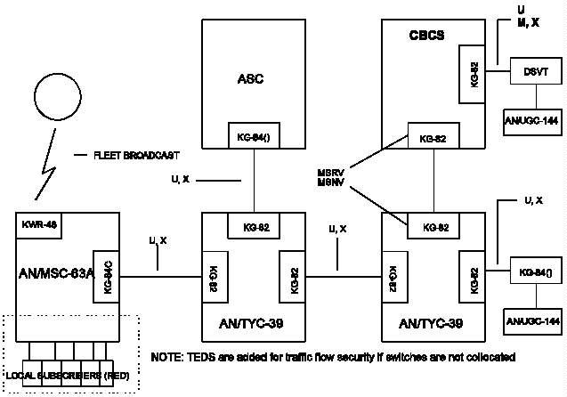 Figure IV-1. Representative Joint Message Switch Network
________________________________________________________________
c. Modes of Operation. As discussed in CJCSM 6231.03A,
interfaces between TTY terminals and the MS will usually be
configured for Mode I or II operation. (The AN/UGC-144 can
be configured to operate in Mode VI.) Trunks between
AN/TYC-39s will operate in Mode I using the message control
block (MCB) feature, and the AN/TYC-39-AUTODIN access line
will use Mode I or Mode VI.
d. Performance. The AN/TYC-39A, terminals (Modes I or
II) and AUTODIN access line will provide the following
functions.
(1) Switch detection of out-of-sync and generation
of SYNC COMMANDS to the online LKG (Modes I, II, and VI)
automatically.
(2) Rekeying of a synchronized KG-84() (Modes I,
II, and IV).
(3) KG-84C detection of out-of-sync condition in
the synchronous mode.
e. Switch Detection of Out-of-Synchronization.
Normally in Mode II operation, the terminal operator must
detect an out-of-sync condition by monitoring a printer for
garbled text. At a message switch, such as AUTODIN, an
out-of-sync condition is detected by monitoring message
sequence or an end-of-message sequence without a
start-of-message (SOM) sequence. However, the AN/TYC-39A
will monitor the data stream on a character-by-character
basis to determine an out-of-sync condition. This is done
by monitoring the framing characters (start/stop bits) for
asynchronous Mode II interface (Type I or Type II lines).
The criterion for determining out-of-sync for the Type I or
Type II line is 127 receive timing errors (RTEs) while
searching for a start-of-message or 10 RTEs in an
84-character block (Mode II is blocked within the message
switch). Upon detection of the out-of-sync condition, the
message switch will generate commands to the online LKG for
a full-duplex start sequence between an LKG and a KG-84() or
another LKG. The AN/TYC-39A will also detect an out-of-sync
condition while operating synchronously (that is, the
AN/TYC-39A Mode I, Type III line interface) This is done by
monitoring the idle pattern or block parity associated with
the 84-character block. Upon detection of the out-of-sync
condition, the AN/TYC-39A will issue a SYNC COMMAND to the
online LKG for a full-duplex resynchronization between the
LKG and distant KG-84() or LKG.
f. Rekeying a Synchronized KG-84(). If the LKG and
KG-84() are in cryptographic synchronization, the
KG-84() can be rekeyed electronically from the AN/TYC-39A
AKDC. However, at the AN/TYC-39A, the rekeying function is
under operator control.
g. KG-84() Detection of Out-of-Synchronization. The
KG-84() can be configured for asynchronous or synchronous
operation. For the Type I or Type II line interface, the
KG-84() at the TTY terminal will be configured in the
full-duplex asynchronous mode (character framed with
start/stop bits). The KG-84() in this mode of operation
features the capability to monitor out-of-sync and to
generate automatic resync. When an out-of-sync condition
has been detected (about 19 character intervals searching
for missing stop bits), the KG-84() will automatically
initiate resync between the KG-84() and LKG. However, when
the KG-84() is operating synchronously (no start/stop bits)
in Mode I or Mode VI operation, only the KG-84C can detect
an out-of-sync condition, the KG-84A cannot.
2. Joint Staff ICP Pair-Wise Unique Key Tape System. The
Pair-Wise Unique Key Tape System permits up to 80 MSs and
KG-84() equipped ASCs to establish secure connectivity by
providing all the keys necessary for cold-start
cryptosynchronization in a single canister of key tape.
(See Annex B of Appendix D.)
3. KG-83 Certification. Detailed test procedures for
certifying the KG-83 with the KT-83 and performing KT-83
self-test are contained in the SAM-70 Maintenance Manual.
4. Assign Keys for the Local Loops. This paragraph
provides information needed at the AN/TYC-39A to assign keys
within the HUS for the local loops. Specific procedures can
be obtained from the operating manuals for the fill device
used. A local loop is a terminal that can be initially
keyed with electronic keys generated at the AN/TYC-39. The
procedures for initializing the HGX-83/TSEC AKDC have a
secondary effect of generating 1,024 new keys, which may be
distributed to subscribers. These keys must be entered on
the key management log as they are requested from the HUS
location and implemented. Therefore, when servicing local
subscribers, only Command 57 is needed. This command
transfers a key from the HUS location to a fill device. The
HGX-83 obtains the key from the HUS location specified by
address A and loads it into the FILL BUFFER. When requested
by the fill device, the HGX-83 transfers the key from the
FILL BUFFER to the fill device. The transfer from the Fill
Buffer to the fill devices must occur within 7 seconds or
the HGX-83 will destroy the contents of the Fill Buffer
register. Upon completion of a Command 57 for the U-key and
a Command 57 for the X-traffic key, the KG-82 and distant
KG-84() can be loaded. During these load procedures the
U-key must be stored in HUS location 0-299 and the X-traffic
variables must be displaced by 300 locations from the U-key.
Therefore, if the U-key is stored in the Y location, then
the X-traffic key must be stored in Y + 300.
a. LKG and HUS Assignments. The AN/TYC-39A offers four
line types and services a variety of TTY terminals operating
in Mode I or Mode II. The Mode II TTY terminals will be a
combination of ITA #2 (Baudot) and ITA #5 (ASCII). At the
message switch, a Type I line equates to Mode II (ITA #2), a
Type II line is for the Mode II ASCII TTY terminals, a Type
III line is for the Mode I terminals trunking between
AN/TYC-39As and the AUTODIN interface, and a Type IV line is
for any application in which data adapters are used. To aid
in the management of the U- and X-traffic keys within the
HUS and for selection of LKGS, LKGs 1-15 will be assigned to
the Type I line interface, and LKGs 16-30 will be assigned
to the Type II line interface (see Table IV-1). LKGs 31-40
and 46, 47, and 48 will support the Type III line interface.
Therefore, HUS locations 0001-0015 and 0301-0315 will
support ITA #2 Mode II subscriber terminals (Type I line),
and HUS locations 0016-0030 and 0316-0330 will be assigned
to the Type II line (ITA #5, Mode II). For the Type III
line interfaces in support of subscriber terminals, HUS
locations 0031-0037 will be assigned to support Mode I
terminals. For Type III line interfaces used on interswitch
trunking and the AUTODIN interface, only LKGs will be
assigned; HUS locations must be determined from Table IV-1.
Therefore, HUS locations 0001-0015 and 0301-0315 will
support ITA #2 Mode II subscriber terminals. Table IV-1
outlines the LKG and HUS locations for the various line
types. (Type IV lines are not shown. If used, HUS
allocations should be rearranged to accommodate them.)
Following these rules, HUS locations 0001 and 0301 will be
assigned to subscriber #1 (logical line number 01) and the
terminal equipment must be a Mode II (ITA #2) type of
operation. At the AN/TYC-39A message switch, the Mode II
(ITA #2) terminal will be connected to a Type I line
interface using LKG #1. HUS locations 0101 and up will be
reserved for the Pair-Wise Unique Key Tapes in support of
the interswitch trunking and the AUTODIN interface.
_____________________________________________________________
Table IV-1. LKG and HUS Allocation
_____________________________________________________________
HUS Location
X-Traffic Line
LTU Red Patch LKG U-Key Key Type
_____________________________________________________________
0 1 1 0001 0301 I
1 2 2 0002 0302 I
2 3 3 0003 0303 I
3 4 4 0004 0304 I
4 5 5 0005 0305 I
5 CONTROL + CHANNEL (OX-54)
6 6 6 0006 0306 I
7 7 7 0007 0306 I
8 8 8 0008 0308 I
9 9 9 0009 0309 I
10 10 10 0010 0310 I
11 CONTROL + CHANNEL (OX-54)
12 1 11 0011 0311 I
13 2 12 0012 0312 I
14 3 13 0013 0313 I
15 4 14 0014 0314 I
16 5 15 0015 0315 I
17 CONTROL + CHANNEL (OX-54)
18 6 16 0016 0316 II 1/
19 7 17 0017 0317 II
20 8 18 0018 0318 II
21 9 19 0019 0319 II
22 10 20 0020 0320 II
23 CONTROL + CHANNEL (OX-54)
25 1 21 0021 0321 II
26 2 22 0022 0322 II
27 3 23 0023 0323 II
28 4 24 0024 0324 II
29 5 25 0025 0325 II
32 6 26 0026 0326 II
33 7 27 0027 0327 II
34 8 28 0028 0328 II
35 9 29 0029 0329 II
36 10 30 0030 0330 II
38 1 31 0031 0331 III
39 2 32 0032 0332 III
40 3 33 0033 0333 III
41 4 34 0034 0334 III
42 5 35 0035 0335 III
44 6 36 0036 0336 III
45 7 37 0037 0037 III
46 8 38 -- -- TRUNKING
47 9 39 -- -- TRUNKING
48 10 40 -- -- TRUNKING
50 1 41 17
51 2 42 18 TDIG
52 3 43 19 J-1
53 4 44 20
54 5 45 21
55 CONTROL + CHANNEL (OX-54) III
57 6 46 -- -- AUTODIN
58 7 47 -- -- AUTODIN
59 8 48 -- -- AUTODIN
60 9
61 10
62 CONTROL + CHANNEL (OX-54)
_________
1/ The Type II line interface can use diphase modem data at
rates 1,200 baud.
_____________________________________________________________
b. Fill Device Usage. The AN/CYZ-10 DTD, KYK-13, and
KYX-15 fill devices are interchangeable for holding and
filling key material. Whenever hard-copy keying material is
used, the KOI-18 tape reader must be used. Fill devices are
loaded using Command 57. This command requests a key from
the HUS location in ADRS A and transfers the key to the fill
buffer. The fill buffer is the interface for a keying
device and is used to load the electronic devices that will,
in turn, manually load the LKG(s) and KG-84()(s).
5. Loading KG-82s and KG-84()s. After the fill device is
loaded, the KG-82 and then the remote KG-84() must be loaded
with the same U- and X-traffic key. The KG-82 should be set
for Position #2, which equates to the redundant sync mode
(FCTN Position #2). After the KG-82 is loaded, the
corresponding KG-84() can then be loaded. The U- and
X-traffic keys will be the same ones loaded into the
corresponding KG-82. The KG-84() must be strapped correctly
and all switches must be set to support a Type I line
interface at the AN/TYC-39A. For details on the technical
characteristics for this interface, see CJCSM 6231.03A.
6. Rekeying a KG-84(). An operator at the AN/TYC-39A can
rekey a KG-84() via the HGX-83. During the rekeying
process, the message switch supervisor may want to inhibit
the traffic on the subscriber loop to be rekeyed. Also,
before rekeying a loop, the switch operator should load a
keying device with the original U- and X-traffic keys.
Thus, if rekeying is not successful, the KG-82 can be
manually loaded with the U- and X-keys. The KG-84() may
also have to be loaded. It is assumed that a keying device
with identical U- and X-traffic keys would be at the
subscriber location. Also, the KG-82 and KG-84() must be in
secure operation before activating the rekeying command.
The rekeying command is Command 23.
7. Loading KG-82 to KG-82 (Trunking). Interswitch trunks
between AN/TYC-39s will establish cold start crypto
initialization using the procedures described in the
applicable JSICP LOI (see Appendix D). At each switch, key
tape will be pre-positioned and the KOI-18 tape reader must
be used. The KOI-18 can be used to load the HUS. However,
the KOI-18 cannot be used to load the KG-82 via the HGX-82.
Therefore, to reduce the number of steps, the KOI-18 should
only be used to load another fill device (KYK-13, KYX-15, or
DTD).
8. External Interface (AUTODIN). KG-84()s at AUTODIN
switch are loaded using procedures described in the
applicable JSICP LOI. It is assumed that the KG-84() is
strapped and switches are set to support a Mode I interface
as described in CJCSM 6231.03A.
9. Point-to-Point Operation KG-84A to KG-84A. In some
deployments, the AN/TYC-39A message switch may not be
needed, and only subscriber terminals will be deployed.
With these types of scenarios, the KG-84A equipment will be
operating point-to-point with other KG-84A/Cs. See
MCM-166-91 for joint doctrine for keying KG-84A/C secured
point-to-point circuits. This document mandates that OTAR
be used to key nearly all KG-84A/C secured point-to-point
circuits that are operated by DOD elements. OTAR procedures
for these KG-84A/Cs are contained in NAG-16D and are
excerpted in Appendix B. If the responsible commander opts
not to rekey KG-84A/C circuits by OTAR, a variety of
cryptoperiods are authorized, the most common being daily
change of TEK or monthly TEK change with daily update.
a. OTAR, using quarterly cryptoperiod KEK and manual
keying (MK) procedures, is the normal means of replacing
KG-84A TEK in point-to-point applications. OTAR TEK should
normally be generated by the KG-83 and distributed to the
net control station in AN/CYZ-10, KYK-13, or KYX-15 fill
devices, but OTAR TEK in tape form may also be used. When
operationally feasible, OTAR KEK should also be generated by
the KG-83 and distributed to both users in fill devices.
Where this procedure is not feasible, OTAR KEK in tape form
may be used. Start-up KEK may be used to activate circuits
and nets that distribute TEK by OTAR. See NAG-16D.
NOTE: Use of the FILL V mode is not authorized.
b. If the responsible commander opts not to replace TEK
by OTAR, TEK may be generated by the KG-83 and furnished to
both stations in fill devices, or tape TEK may be used,
provided the affected segments are not used for any other
purpose.
10. Message Switch Traffic Flow Security. Normally,
trunking between the AN/TYC-39A MSs is Mode I operating at
1,200 baud and is encrypted full period using LKGs.
Therefore, all traffic between switches is secured with the
LKGs and configured to provide traffic flow security. When
TRI-TAC transmission equipment is used, the LKGs will still
be employed to perform full-period encryption and provide
traffic flow security. Traffic flow security for TRI-TAC
digital groups will be achieved by employing TEDs. This is
for trunking between a message switch and circuit switch in
support of data terminals connected to the circuit switch.
These trunks are in support of the Type IV line interface at
the message switch and dial-up data subscribers off the
circuit switch.
11. Y-Community Traffic. As noted in CJCSM 6231.03A, the
joint message switching network comprises a mixture of R-
and Y-community subscribers. Procedures required to
accredit the AN/TYC-39A MS as an SCI facility (SCIF) are
provided in CJCSM 6231.07A. A waiver is in effect to allow
TS/SCI CBCS subscribers dial-up access to the AN/TYC-39A.
U-keys are issued to these subscribers on tape. Those keys
are stored in HUS locations 26 and 27 at the CBCSs that
support SCIFs. Specific rules for safeguarding and use of
these keys are prescribed as conditions for the waiver. The
actual waiver or any implementing directives should be
consulted when planning for or using this capability.
12. AN/TYC-39A Reports Classification. Below are security
guidelines for the AN/TYC-39A MS and associated automatic
reports.
a. Classification Authority. SSO, Defense Intelligence
Agency (DIA) exercises original security classification
authority for the Tactical Defense Special Security
Communications System (TDSSCS) and information processed by
the AN/TYC-39. Actual routing indicators are not to be
associated with activities and geographic locations unless
appropriately classified and approved by the original class-
ification authority. If necessary, derivative classifica-
tion may be used to tentatively classify information pending
review by the SSO DIA. All unclassified information will be
handled as FOR OFFICIAL USE ONLY. SSO DIA is the point of
contact for Freedom of Information releases in cases of
appeal to release FOR OFFICIAL USE ONLY information.
b. Daily Cumulative Statistics (CUM STATS). Classify
CUM STATS CONFIDENTIAL when Y-traffic and circuit status are
contained therein. Identify further tributary circuit data
for Y-community subscribers by routing indicators and
command communication service designators.
c. Routing Indicators (RIs). RIs, when associated with
unclassified activities or unclassified messages, are
unclassified. Classify Y-community RI table and channel
parameters CONFIDENTIAL.
d. System and Cumulative Statistics (STATS). Classify
STATS CONFIDENTIAL. Extracts of R-community statistics are
unclassified.
e. Printer Printouts. The supervisor, traffic service,
and maintenance printer printouts are CONFIDENTIAL.
f. Service Messages. Individual service messages are
unclassified.
g. Transmission Control Code (TCC). Any TCC code with
its ID is unclassified. Classify any actual TCC with its
associated routing indicator CONFIDENTIAL. However, this
combination may be unclassified based on a case-by-case
determination.
h. Special Access Data. Information stating that an
individual is approved for access to SCI or SIOP-ESI is
unclassified, FOR OFFICIAL USE ONLY, or CONFIDENTIAL, at the
discretion of the originator, depending on the information
disclosed and other classification criteria. In any event,
classify a listing that reveals the names and job titles of
all SCI and/or SIOP-ESI approved personnel of an
organization or company not lower than CONFIDENTIAL.
i. DSSCS. The term "Defense Special Security
Communications System (DSSCS)" is unclassified when
unaccompanied by other descriptive data.
j. Magnetic Storage Devices. Classify long- and
short-history magnetic tapes, disks, and memory storage
devices TOP SECRET/SIOP-ESI/Contains CODEWORD/Sensitive
Compartmented Information/US ONLY. Classify other magnetic
tapes, disks, and memory devices (such as program storage
media) in accordance with the classification of the data or
information they contain.
k. Y RIs. One or more Y-community routing indicators
are unclassified; RI table and channel parameters are
CONFIDENTIAL.
l. Use of NOFORN or US ONLY. DOD 5200.1-R authorizes
the marking of "NOFORN" as a designator for "Not Releasable
to Foreign Nationals" in electrically transmitted messages
and automated data processing products that include the
appropriate documents covered in this publication. However,
the NOFORN and REL TO designators are being phased out, to
be replaced by US ONLY and US and (designated nation) ONLY.
The new terms are already required on hard-copy
communications. NOFORN and REL TO will continue in use on
electronic communications until worldwide systems are
modified to accept the new designators.
Figure IV-1. Representative Joint Message Switch Network
________________________________________________________________
c. Modes of Operation. As discussed in CJCSM 6231.03A,
interfaces between TTY terminals and the MS will usually be
configured for Mode I or II operation. (The AN/UGC-144 can
be configured to operate in Mode VI.) Trunks between
AN/TYC-39s will operate in Mode I using the message control
block (MCB) feature, and the AN/TYC-39-AUTODIN access line
will use Mode I or Mode VI.
d. Performance. The AN/TYC-39A, terminals (Modes I or
II) and AUTODIN access line will provide the following
functions.
(1) Switch detection of out-of-sync and generation
of SYNC COMMANDS to the online LKG (Modes I, II, and VI)
automatically.
(2) Rekeying of a synchronized KG-84() (Modes I,
II, and IV).
(3) KG-84C detection of out-of-sync condition in
the synchronous mode.
e. Switch Detection of Out-of-Synchronization.
Normally in Mode II operation, the terminal operator must
detect an out-of-sync condition by monitoring a printer for
garbled text. At a message switch, such as AUTODIN, an
out-of-sync condition is detected by monitoring message
sequence or an end-of-message sequence without a
start-of-message (SOM) sequence. However, the AN/TYC-39A
will monitor the data stream on a character-by-character
basis to determine an out-of-sync condition. This is done
by monitoring the framing characters (start/stop bits) for
asynchronous Mode II interface (Type I or Type II lines).
The criterion for determining out-of-sync for the Type I or
Type II line is 127 receive timing errors (RTEs) while
searching for a start-of-message or 10 RTEs in an
84-character block (Mode II is blocked within the message
switch). Upon detection of the out-of-sync condition, the
message switch will generate commands to the online LKG for
a full-duplex start sequence between an LKG and a KG-84() or
another LKG. The AN/TYC-39A will also detect an out-of-sync
condition while operating synchronously (that is, the
AN/TYC-39A Mode I, Type III line interface) This is done by
monitoring the idle pattern or block parity associated with
the 84-character block. Upon detection of the out-of-sync
condition, the AN/TYC-39A will issue a SYNC COMMAND to the
online LKG for a full-duplex resynchronization between the
LKG and distant KG-84() or LKG.
f. Rekeying a Synchronized KG-84(). If the LKG and
KG-84() are in cryptographic synchronization, the
KG-84() can be rekeyed electronically from the AN/TYC-39A
AKDC. However, at the AN/TYC-39A, the rekeying function is
under operator control.
g. KG-84() Detection of Out-of-Synchronization. The
KG-84() can be configured for asynchronous or synchronous
operation. For the Type I or Type II line interface, the
KG-84() at the TTY terminal will be configured in the
full-duplex asynchronous mode (character framed with
start/stop bits). The KG-84() in this mode of operation
features the capability to monitor out-of-sync and to
generate automatic resync. When an out-of-sync condition
has been detected (about 19 character intervals searching
for missing stop bits), the KG-84() will automatically
initiate resync between the KG-84() and LKG. However, when
the KG-84() is operating synchronously (no start/stop bits)
in Mode I or Mode VI operation, only the KG-84C can detect
an out-of-sync condition, the KG-84A cannot.
2. Joint Staff ICP Pair-Wise Unique Key Tape System. The
Pair-Wise Unique Key Tape System permits up to 80 MSs and
KG-84() equipped ASCs to establish secure connectivity by
providing all the keys necessary for cold-start
cryptosynchronization in a single canister of key tape.
(See Annex B of Appendix D.)
3. KG-83 Certification. Detailed test procedures for
certifying the KG-83 with the KT-83 and performing KT-83
self-test are contained in the SAM-70 Maintenance Manual.
4. Assign Keys for the Local Loops. This paragraph
provides information needed at the AN/TYC-39A to assign keys
within the HUS for the local loops. Specific procedures can
be obtained from the operating manuals for the fill device
used. A local loop is a terminal that can be initially
keyed with electronic keys generated at the AN/TYC-39. The
procedures for initializing the HGX-83/TSEC AKDC have a
secondary effect of generating 1,024 new keys, which may be
distributed to subscribers. These keys must be entered on
the key management log as they are requested from the HUS
location and implemented. Therefore, when servicing local
subscribers, only Command 57 is needed. This command
transfers a key from the HUS location to a fill device. The
HGX-83 obtains the key from the HUS location specified by
address A and loads it into the FILL BUFFER. When requested
by the fill device, the HGX-83 transfers the key from the
FILL BUFFER to the fill device. The transfer from the Fill
Buffer to the fill devices must occur within 7 seconds or
the HGX-83 will destroy the contents of the Fill Buffer
register. Upon completion of a Command 57 for the U-key and
a Command 57 for the X-traffic key, the KG-82 and distant
KG-84() can be loaded. During these load procedures the
U-key must be stored in HUS location 0-299 and the X-traffic
variables must be displaced by 300 locations from the U-key.
Therefore, if the U-key is stored in the Y location, then
the X-traffic key must be stored in Y + 300.
a. LKG and HUS Assignments. The AN/TYC-39A offers four
line types and services a variety of TTY terminals operating
in Mode I or Mode II. The Mode II TTY terminals will be a
combination of ITA #2 (Baudot) and ITA #5 (ASCII). At the
message switch, a Type I line equates to Mode II (ITA #2), a
Type II line is for the Mode II ASCII TTY terminals, a Type
III line is for the Mode I terminals trunking between
AN/TYC-39As and the AUTODIN interface, and a Type IV line is
for any application in which data adapters are used. To aid
in the management of the U- and X-traffic keys within the
HUS and for selection of LKGS, LKGs 1-15 will be assigned to
the Type I line interface, and LKGs 16-30 will be assigned
to the Type II line interface (see Table IV-1). LKGs 31-40
and 46, 47, and 48 will support the Type III line interface.
Therefore, HUS locations 0001-0015 and 0301-0315 will
support ITA #2 Mode II subscriber terminals (Type I line),
and HUS locations 0016-0030 and 0316-0330 will be assigned
to the Type II line (ITA #5, Mode II). For the Type III
line interfaces in support of subscriber terminals, HUS
locations 0031-0037 will be assigned to support Mode I
terminals. For Type III line interfaces used on interswitch
trunking and the AUTODIN interface, only LKGs will be
assigned; HUS locations must be determined from Table IV-1.
Therefore, HUS locations 0001-0015 and 0301-0315 will
support ITA #2 Mode II subscriber terminals. Table IV-1
outlines the LKG and HUS locations for the various line
types. (Type IV lines are not shown. If used, HUS
allocations should be rearranged to accommodate them.)
Following these rules, HUS locations 0001 and 0301 will be
assigned to subscriber #1 (logical line number 01) and the
terminal equipment must be a Mode II (ITA #2) type of
operation. At the AN/TYC-39A message switch, the Mode II
(ITA #2) terminal will be connected to a Type I line
interface using LKG #1. HUS locations 0101 and up will be
reserved for the Pair-Wise Unique Key Tapes in support of
the interswitch trunking and the AUTODIN interface.
_____________________________________________________________
Table IV-1. LKG and HUS Allocation
_____________________________________________________________
HUS Location
X-Traffic Line
LTU Red Patch LKG U-Key Key Type
_____________________________________________________________
0 1 1 0001 0301 I
1 2 2 0002 0302 I
2 3 3 0003 0303 I
3 4 4 0004 0304 I
4 5 5 0005 0305 I
5 CONTROL + CHANNEL (OX-54)
6 6 6 0006 0306 I
7 7 7 0007 0306 I
8 8 8 0008 0308 I
9 9 9 0009 0309 I
10 10 10 0010 0310 I
11 CONTROL + CHANNEL (OX-54)
12 1 11 0011 0311 I
13 2 12 0012 0312 I
14 3 13 0013 0313 I
15 4 14 0014 0314 I
16 5 15 0015 0315 I
17 CONTROL + CHANNEL (OX-54)
18 6 16 0016 0316 II 1/
19 7 17 0017 0317 II
20 8 18 0018 0318 II
21 9 19 0019 0319 II
22 10 20 0020 0320 II
23 CONTROL + CHANNEL (OX-54)
25 1 21 0021 0321 II
26 2 22 0022 0322 II
27 3 23 0023 0323 II
28 4 24 0024 0324 II
29 5 25 0025 0325 II
32 6 26 0026 0326 II
33 7 27 0027 0327 II
34 8 28 0028 0328 II
35 9 29 0029 0329 II
36 10 30 0030 0330 II
38 1 31 0031 0331 III
39 2 32 0032 0332 III
40 3 33 0033 0333 III
41 4 34 0034 0334 III
42 5 35 0035 0335 III
44 6 36 0036 0336 III
45 7 37 0037 0037 III
46 8 38 -- -- TRUNKING
47 9 39 -- -- TRUNKING
48 10 40 -- -- TRUNKING
50 1 41 17
51 2 42 18 TDIG
52 3 43 19 J-1
53 4 44 20
54 5 45 21
55 CONTROL + CHANNEL (OX-54) III
57 6 46 -- -- AUTODIN
58 7 47 -- -- AUTODIN
59 8 48 -- -- AUTODIN
60 9
61 10
62 CONTROL + CHANNEL (OX-54)
_________
1/ The Type II line interface can use diphase modem data at
rates 1,200 baud.
_____________________________________________________________
b. Fill Device Usage. The AN/CYZ-10 DTD, KYK-13, and
KYX-15 fill devices are interchangeable for holding and
filling key material. Whenever hard-copy keying material is
used, the KOI-18 tape reader must be used. Fill devices are
loaded using Command 57. This command requests a key from
the HUS location in ADRS A and transfers the key to the fill
buffer. The fill buffer is the interface for a keying
device and is used to load the electronic devices that will,
in turn, manually load the LKG(s) and KG-84()(s).
5. Loading KG-82s and KG-84()s. After the fill device is
loaded, the KG-82 and then the remote KG-84() must be loaded
with the same U- and X-traffic key. The KG-82 should be set
for Position #2, which equates to the redundant sync mode
(FCTN Position #2). After the KG-82 is loaded, the
corresponding KG-84() can then be loaded. The U- and
X-traffic keys will be the same ones loaded into the
corresponding KG-82. The KG-84() must be strapped correctly
and all switches must be set to support a Type I line
interface at the AN/TYC-39A. For details on the technical
characteristics for this interface, see CJCSM 6231.03A.
6. Rekeying a KG-84(). An operator at the AN/TYC-39A can
rekey a KG-84() via the HGX-83. During the rekeying
process, the message switch supervisor may want to inhibit
the traffic on the subscriber loop to be rekeyed. Also,
before rekeying a loop, the switch operator should load a
keying device with the original U- and X-traffic keys.
Thus, if rekeying is not successful, the KG-82 can be
manually loaded with the U- and X-keys. The KG-84() may
also have to be loaded. It is assumed that a keying device
with identical U- and X-traffic keys would be at the
subscriber location. Also, the KG-82 and KG-84() must be in
secure operation before activating the rekeying command.
The rekeying command is Command 23.
7. Loading KG-82 to KG-82 (Trunking). Interswitch trunks
between AN/TYC-39s will establish cold start crypto
initialization using the procedures described in the
applicable JSICP LOI (see Appendix D). At each switch, key
tape will be pre-positioned and the KOI-18 tape reader must
be used. The KOI-18 can be used to load the HUS. However,
the KOI-18 cannot be used to load the KG-82 via the HGX-82.
Therefore, to reduce the number of steps, the KOI-18 should
only be used to load another fill device (KYK-13, KYX-15, or
DTD).
8. External Interface (AUTODIN). KG-84()s at AUTODIN
switch are loaded using procedures described in the
applicable JSICP LOI. It is assumed that the KG-84() is
strapped and switches are set to support a Mode I interface
as described in CJCSM 6231.03A.
9. Point-to-Point Operation KG-84A to KG-84A. In some
deployments, the AN/TYC-39A message switch may not be
needed, and only subscriber terminals will be deployed.
With these types of scenarios, the KG-84A equipment will be
operating point-to-point with other KG-84A/Cs. See
MCM-166-91 for joint doctrine for keying KG-84A/C secured
point-to-point circuits. This document mandates that OTAR
be used to key nearly all KG-84A/C secured point-to-point
circuits that are operated by DOD elements. OTAR procedures
for these KG-84A/Cs are contained in NAG-16D and are
excerpted in Appendix B. If the responsible commander opts
not to rekey KG-84A/C circuits by OTAR, a variety of
cryptoperiods are authorized, the most common being daily
change of TEK or monthly TEK change with daily update.
a. OTAR, using quarterly cryptoperiod KEK and manual
keying (MK) procedures, is the normal means of replacing
KG-84A TEK in point-to-point applications. OTAR TEK should
normally be generated by the KG-83 and distributed to the
net control station in AN/CYZ-10, KYK-13, or KYX-15 fill
devices, but OTAR TEK in tape form may also be used. When
operationally feasible, OTAR KEK should also be generated by
the KG-83 and distributed to both users in fill devices.
Where this procedure is not feasible, OTAR KEK in tape form
may be used. Start-up KEK may be used to activate circuits
and nets that distribute TEK by OTAR. See NAG-16D.
NOTE: Use of the FILL V mode is not authorized.
b. If the responsible commander opts not to replace TEK
by OTAR, TEK may be generated by the KG-83 and furnished to
both stations in fill devices, or tape TEK may be used,
provided the affected segments are not used for any other
purpose.
10. Message Switch Traffic Flow Security. Normally,
trunking between the AN/TYC-39A MSs is Mode I operating at
1,200 baud and is encrypted full period using LKGs.
Therefore, all traffic between switches is secured with the
LKGs and configured to provide traffic flow security. When
TRI-TAC transmission equipment is used, the LKGs will still
be employed to perform full-period encryption and provide
traffic flow security. Traffic flow security for TRI-TAC
digital groups will be achieved by employing TEDs. This is
for trunking between a message switch and circuit switch in
support of data terminals connected to the circuit switch.
These trunks are in support of the Type IV line interface at
the message switch and dial-up data subscribers off the
circuit switch.
11. Y-Community Traffic. As noted in CJCSM 6231.03A, the
joint message switching network comprises a mixture of R-
and Y-community subscribers. Procedures required to
accredit the AN/TYC-39A MS as an SCI facility (SCIF) are
provided in CJCSM 6231.07A. A waiver is in effect to allow
TS/SCI CBCS subscribers dial-up access to the AN/TYC-39A.
U-keys are issued to these subscribers on tape. Those keys
are stored in HUS locations 26 and 27 at the CBCSs that
support SCIFs. Specific rules for safeguarding and use of
these keys are prescribed as conditions for the waiver. The
actual waiver or any implementing directives should be
consulted when planning for or using this capability.
12. AN/TYC-39A Reports Classification. Below are security
guidelines for the AN/TYC-39A MS and associated automatic
reports.
a. Classification Authority. SSO, Defense Intelligence
Agency (DIA) exercises original security classification
authority for the Tactical Defense Special Security
Communications System (TDSSCS) and information processed by
the AN/TYC-39. Actual routing indicators are not to be
associated with activities and geographic locations unless
appropriately classified and approved by the original class-
ification authority. If necessary, derivative classifica-
tion may be used to tentatively classify information pending
review by the SSO DIA. All unclassified information will be
handled as FOR OFFICIAL USE ONLY. SSO DIA is the point of
contact for Freedom of Information releases in cases of
appeal to release FOR OFFICIAL USE ONLY information.
b. Daily Cumulative Statistics (CUM STATS). Classify
CUM STATS CONFIDENTIAL when Y-traffic and circuit status are
contained therein. Identify further tributary circuit data
for Y-community subscribers by routing indicators and
command communication service designators.
c. Routing Indicators (RIs). RIs, when associated with
unclassified activities or unclassified messages, are
unclassified. Classify Y-community RI table and channel
parameters CONFIDENTIAL.
d. System and Cumulative Statistics (STATS). Classify
STATS CONFIDENTIAL. Extracts of R-community statistics are
unclassified.
e. Printer Printouts. The supervisor, traffic service,
and maintenance printer printouts are CONFIDENTIAL.
f. Service Messages. Individual service messages are
unclassified.
g. Transmission Control Code (TCC). Any TCC code with
its ID is unclassified. Classify any actual TCC with its
associated routing indicator CONFIDENTIAL. However, this
combination may be unclassified based on a case-by-case
determination.
h. Special Access Data. Information stating that an
individual is approved for access to SCI or SIOP-ESI is
unclassified, FOR OFFICIAL USE ONLY, or CONFIDENTIAL, at the
discretion of the originator, depending on the information
disclosed and other classification criteria. In any event,
classify a listing that reveals the names and job titles of
all SCI and/or SIOP-ESI approved personnel of an
organization or company not lower than CONFIDENTIAL.
i. DSSCS. The term "Defense Special Security
Communications System (DSSCS)" is unclassified when
unaccompanied by other descriptive data.
j. Magnetic Storage Devices. Classify long- and
short-history magnetic tapes, disks, and memory storage
devices TOP SECRET/SIOP-ESI/Contains CODEWORD/Sensitive
Compartmented Information/US ONLY. Classify other magnetic
tapes, disks, and memory devices (such as program storage
media) in accordance with the classification of the data or
information they contain.
k. Y RIs. One or more Y-community routing indicators
are unclassified; RI table and channel parameters are
CONFIDENTIAL.
l. Use of NOFORN or US ONLY. DOD 5200.1-R authorizes
the marking of "NOFORN" as a designator for "Not Releasable
to Foreign Nationals" in electrically transmitted messages
and automated data processing products that include the
appropriate documents covered in this publication. However,
the NOFORN and REL TO designators are being phased out, to
be replaced by US ONLY and US and (designated nation) ONLY.
The new terms are already required on hard-copy
communications. NOFORN and REL TO will continue in use on
electronic communications until worldwide systems are
modified to accept the new designators.
CHAPTER V
AN/TSQ-111 COMMUNICATIONS NODAL CONTROL ELEMENT AND
TRANSMISSION SYSTEM COMSEC EQUIPMENT AND PROCEDURES
1. Introduction. This chapter describes COMSEC equipment
used within the AN/TSQ-111 CNCE and at the transmission
assemblages to support DOW functions and DTGs egressing from
the CNCE. It provides information to enable system planners
to determine needed COMSEC equipment and keys to support
DOWs and COMSEC within the transmission network.
2. General. COMSEC equipment developed to support CNCE
security requirements is the same as previously described
for the MS and the CS. The COMSEC equipment in the CS is
under processor control, whereas the COMSEC equipment in the
MS and the CNCE is under operator control. The difference
between the operation at the AN/TYC-39A MS and the CNCE is
the out-of-sync (OOS) detection scheme and KG-84() usage.
Within the AN/TYC-39A, OOS detection is done by the switch
processor; at the CNCE, OOS detection is provided externally
from the CNCE processor. Also, OOS detection is only
provided at one end of the link. In the message switch
network, all subscriber terminals are connected directly to
the MS, and KG-84()s at subscriber terminals are assigned to
an LKG within the AN/TYC-39. Most KG-84()s used to support
CNCE/DOW functions must operate KG-84()-to-KG-84(). Thus,
KG-84()s operating with the AN/TYC-39A can be rekeyed
automatically, but the majority of KG-84()s used with the
CNCE must be manually rekeyed.
a. Equipment Configuration. For the CNCE, a fully
populated CEF consists of 2 HGF-92s, 2 HGX-82s, 16 KG-82s, 1
HGX-83, 1 KG-83, 4 HGF-94s, and 12 KG-94 TEDS. Table V-1
lists the TRI-TAC and non-TRI-TAC COMSEC equipment
associated with a CNCE.
_____________________________________________________________
Table V-1. AN/TSQ-111 COMSEC Items
_____________________________________________________________
COMSEC Eq Qty Spare Total Remarks
_____________________________________________________________
HGF-92 2 0 2
HGF-94 4 0 4
HGX-82 2 0 2
HGX-83 1 1 1
KG-94 12 1 13
KG-82 16 1 17
KG-83 1 0 2
KY-58 1 0 1 Non-TRI-TAC
KY-68 1 0 1
KY-75 1 0 1 Non-TRI-TAC
KOI-18 1/ 1 0 1 Tape Reader
Fill Cable 3 0 3
KYK-13 1/ 5 0 5 Electronic Transfer
Device
KYX-15 1/ 1 0 1 Net Control Device
_________
1/ The AN/CYZ-10 DTD will replace these devices. DTDs will
be used based on availability until they are fully
fielded. The utility of DTDs will be limited until the
JKMS is fully implemented.
_____________________________________________________________
b. System Description. The 16 KG-82s in the CNCE are
used to secure DOWs which can be telemetry, teletype, or
links from one CNCE processor to another CNCE processor.
The telemetry system provides the CNCE controller with
real-time status information on cable systems, RF
transmission systems, multiplexers, modems, and AN/TSQ-146
multiplexer terminals. This status information and the
results of 2-kbps loop-back tests made through the network
are used for network quality assessment and fault isolation.
Telemetry data is generated at 15-characters per second and
transmitted to the CNCE at a 75-bps, 150-bps, or 2-kbps
transmission rate. Within the CNCE, 75-bps or 150-bps data
can be entered directly into the communication interface
controller (CIC) to be processed as independent status data
for each assemblage or can be combined at the CNCE and then
entered at a 2-kbps transmission rate. If entered at the
2-kbps transmission rate, the combined telemetry data is
decombined within the CIC and processed as independent
status data for each assemblage. The last approach would
reduce the number of ports used at the CIC. If the
assemblages are in series, the combined telemetry data
enters the CNCE at the 2-kbps transmission rate and is
entered directly into the CIC and decombined as previously
explained. This configuration reduces the number of LKGs
needed at the CNCE. Figure V-1 depicts the Orderwire
Control Unit (OCU), which would be located at one of the
assemblages interfaced directly with the equivalent
equipment at the CNCE. Only the telemetry combiner (TC) and
telemetry decombiner (TD) functions of the OCU are shown.
Also provided in Figure V-1 are the communication equipment
support element (CESE) telemetry data requirements and
equipment parameters. Rules for DOW operation in this
configuration are shown in Table V-2. KG-84() strapping
options and switch settings for DOW operation are shown in
Appendix F.
____________________________________________________________________
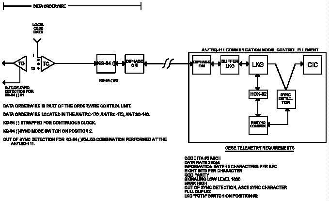 Figure V-1. Data Orderwire to AN/TSQ-111
____________________________________________________________________
_____________________________________________________________
Table V-2. DOW Rules
_____________________________________________________________
1. KG-84() associated with the TC operates in the SLAVE
CLOCK MODE (Position #2). This should be KG-84() #2.
2. KG-84() associated with the TD operates in the MASTER
CLOCK MODE (Position #1). This should be KG-84() #1.
3. TD monitors for loss of sync and issues a SYNC CM to
KG-84() #1.
4. Loss of sync is detected at only one end of the
circuit for KG-84()s operating point-to-point.
5. Loss of sync is detected at the CNCE/OOS for KG-84()s
directly connected to LKGs. For this operation, loss
of sync is only detected at one end of the circuit.
_____________________________________________________________
3. COMSEC Controller. The CNCE COMSEC controller monitors
the RED side of the 16 LKGs to determine an OOS condition
for the DOWs. When an OOS condition is detected, the COMSEC
controller generates codewords to the HGX-82, which
initiates and verifies synchronization for the affected LKG.
The COMSEC controller can monitor for loss-of-sync in any of
12 possible data formats as outlined in CJCSM 6231.06. The
COMSEC Controller performs many functions and is structured
as depicted in Figure V-1, which includes the sync detection
module (SDM) and the resync control module (RCM).
a. Sync Detection Module. The SDM scans each plain
text received line of the 16 LKGs to determine loss of sync.
The SDM sets time limits, controls all timing and sequences,
generates request messages to the RCM, and receives resync
achieved messages from the RCM. When an OOS condition is
detected by the SDM for a given LKG, a resync request is
transmitted to the RCM. During the LKG sync phase, the SDM
sets the 4.1 seconds time limit for the sync acquisition.
The count is ended when a resync achieved message is
received from the RCM or when the counter has timed-out at
the end of 4.1 seconds. If the LKG remains OOS, another
resync request is sent to the RCM and the time-out counter
is again activated. After three attempts to resync a given
LKG, an OOS condition is declared by the SDM and a channel
status alarm is activated for the affected LKG.
b. Resync Control Module. The RCM handshakes with the
HGX-82s during the LKG synchronization phase. The RCM
generates the sync command that is sent to the LKG via the
HGX-82 and monitors the status of the BUSY indicator (FULL
OPERATE) for a successful sync cycle between the LKG and the
KG-84(). A successful sync cycle is shown when the BUSY
status indicator goes from the ON to the OFF and back to the
ON state. When this occurs, the RCM generates a RESYNC
ACKNOWLEDGE message to the SDM to indicate that resync has
been achieved.
4. Key Management. The CNCE is configured with an
electronic key generator (KG-83), and keys generated by it
or read from a KOI-18 tape reader at the CNCE must be
controlled.
a. Responsibilities. The CNCE controller is
responsible for the control and management of all keys
generated at the CNCE.
b. Accountability. All keys in electronic form will be
accounted for in the key management log. A key management
log will be maintained wherever keys are generated and
stored. The CNCE controller will maintain a key management
log that records all keys generated at the CNCE.
c. Supersession. The CNCE controller is responsible
for the timely and orderly supersession of all keys
generated at the CNCE. The controller should coordinate the
distribution of keys in sufficient time to allow changes
before the end of the cryptoperiod. Whenever a key is
superseded, enter the supersession DTG in the key management
log.
5. Key Generation and HUS Assignment. Specific procedures
for generating keys are contained in Appendix B. When the
HUS is loaded with keys, the CNCE has the classification of
the orderwires and transmission links that must be
protected. For the CNCE application, the CNCE
classification would be SECRET. CNCE rules are:
a. During key assignment, the U-key must be stored in
HUS location 0-299 and the X-key must be displaced by 300
locations for the U-key. Therefore, if the U-key is stored
in the Y location, then the X-key must be stored in Y + 300.
b. A transfer from the fill buffer to the keying device
must occur within 7 seconds or the HGX-83 will destroy the
contents of the fill buffer register. To support DOWs, HUS
locations 0001-0016 have been reserved for the KEK "U" and
0301-0316 are for the TEK "X" as shown in Table V-3.
___________________________________________________________
Table V-3. LKG and HUS Allocation
___________________________________________________________
LKG KEK "U" TEK "X" Station ID Notes
___________________________________________________________
1 0001 0301
2 0002 0302
3 0003 0303
4 0004 0304
5 0005 0305
6 0006 0306
7 0007 0307
8 0008 0308
9 0009 0309
10 0010 0310
11 0011 0311
12 0012 0312
13 0013 0313
14 0014 0314
15 0015 0315
16 0016 0316
0017 0317
Other CNCE Functions
VINSON
DSVT
0032 0332
0333 TED Seed Keys
___________________________________________________________
6. DOW Point-to-Point Operation (KG-84()-to-KG-84()).
Three separate orderwire assemblages are decombined within
the CIC. However, two orderwire assemblages operate on a
link basis, and the encryption scheme is independent of CNCE
COMSEC operation. That is, the KG-84()s do not connect to
LKGs within the CNCE. Thus, the AN/TSQ-146 and distant
AN/TRC-170 orderwire assemblages are combined and encrypted
or decrypted and decombined on a link basis. The KG-84()s
operate point-to-point with another KG-84(). For this type
of operation, the distant AN/TRC-170 could be up to 150 to
175 miles from the AN/TRC-170 collocated with the CNCE.
When the KG-84() is operated point-to-point with another
KG-84() on a full-period circuit, the X-traffic key can be
extended to a 1-month cryptoperiod with daily updates. When
the UPDATE function is activated, a coordinated procedure
between KG-84() operators is required. During this
procedure, the TEK "X" is replaced with a modified TEK "X."
A KEK "U" is not used with the UPDATE function. However,
when a KG-84() is initialized from a cold start, the LDU
register must be initialized. These procedures are used
when no remote rekeying is done.
7. Manual Cooperative Variable Transfer (DSVT-to-DSVT).
These procedures provide manual transfer of keys from one
CNCE to another CNCE. TEDs are initially keyed using a
unique segment of the ICP key tape(s). This segment is
identified as the TED Cold Start key and is used only for
cold start initialization. After secure connectivity
between CNCEs or AN/TRC-170s is established, the controlling
CNCE will electronically generate TED Seed keys (see
Table V-3), which must be electronically transferred between
the CNCEs. For this application, DSVT MCVT procedures will
be implemented. One DSVT at the CNCE will become a
subscriber off the AN/TTC-39(). At the distant CNCE, one of
its DSVTs will also be connected to its collocated CS.
Thus, keys for the DSVTs will be generated by collocated
AN/TTC-39()s. In the MCVT operation, the transferred key
does not alter X- or U-key contents of the DSVTs partici-
pating in the operation. The DSVTs do not use their
resident U-key in the transfer, but use a rekeying key
stored in each of the KYX-15s or DTDs. Both KYX-15s must
contain the same rekeying key, and the sending KYX-15
(controlling CNCE) must also contain the TED Seed key(s) to
be transferred. Electronically generated keys used as TED
Seed keys on TED links must be destroyed (fill device or
AKDC location zeroized) immediately after establishing
synchronization. To implement MCVT procedures, the TED
protected MUX group at the CNCE or AN/TRC-170 must be
operational. For this scenario, the TED at the CNCE will be
used. The DSVT at the controlling CNCE will be assigned as
a subscriber off the CS. At the distant CNCE, a DSVT will
also be assigned as a subscriber off its collocated CS.
Thus, secure communications can be established between CNCEs
using DSVTs and switch generated keys. The next step is to
load the KYX-15 at the controlling CNCE with the rekeying
key and TED Seed keys. TED Seed keys for this operation
will be transferred from the AKDC to the fill device
(Table V-3). The TED Seed keys can also be generated
directly from the KG-83 to the fill device. The latter
approach reduces the number of required steps. At the
distant CNCE, the KYX-15 must also be loaded with the
identical rekeying key. At the completion of the above
steps, MCVT procedures can be activated. After completion
of the TED Seed key(s) transfer, the TED Cold Start key that
was used to initialize the TEDs must be replaced with the
TED Seed key. To implement MCVT procedures requires the
following steps:
a. Activate TEDs with the TED Cold Start key.
b. Load DSVTs and assign directory numbers at both
CNCEs.
c. Load the KYX-15 or DTD at the controlling CNCE with
the identified rekeying key using the KOI-18.
d. Load the KYX-15 or DTD at the controlling CNCE with
TED Seed keys using HGX-83 Command 57.
e. Use MCVT-DSVT procedures to transfer TED Seed
key(s). See NAG-16D/TSEC for more information about MCVT
procedures.
f. Replace the TED Cold Start key with the TED Seed
key.
g. After TED synchronization in the TED Seed key,
zeroize the KYX-15(s) or DTDs and HUS storage location(s)
(Command 05) for the electronically generated Seed key that
is operational. (In the MSE, the HUS storage locations for
operational TED keys are not erased.)
8. Transmission Systems COMSEC Procedures. To meet
tactical security requirements, TEDs have been implemented
within the AN/TTC-39(), ULCSs, MSE, AN/TYC-39A, AN/TSQ-111,
AN/TSQ-146, AN/TRC-170, AN/TRC-173, and the AN/TSC-85B,
AN/TSC-93B, AN/TSC-94A, AN/TSC-100A satellite terminals.
This equipment can be deployed in various configurations to
provide the needed security. Table V-4 lists the COMSEC
complement of various types of transmission equipment.
Certainly, it is not necessary to encrypt and decrypt on a
link basis. A representative joint transmission network
showing a possible employment of TEDs is shown in
Figure V-2. Listed below are some guidelines for TED usage
when the above equipment is deployed.
__________________________________________________________________
Table V-4. Transmission Equipment COMSEC Complement
__________________________________________________________________
Equipment TED KG-84() VINSON
__________________________________________________________________
AN/TSC-94A(V) 2 2 1
AN/TSC-94A(V)2 1 1 1
AN/TSC-100A(V)1 6 1 2
AN/TSC-100A(V)2 5 1 2
AN/TSC-85B 4 1
AN/TSC-93B 2 1/ 1
AN/TSQ-146(V)1/2 4 3 2/ 2
AN/TSQ-146(V)3 4 3 2/ 1
AN/TRC-170 2 2 1
AN/TRC-173 3/ 2 1 1
AN/TRC-174 3/ 2 1
AN/TRC-175 3/ 1 1
AN/MRC-142 2 1
AN/TRC-138() 3/ 1
AN/TRC-190(V) 1
AN/TRC-198(V)1 1
_________
1/ JCSE AN/TSC-93Bs have 3.
2/ one is a spare.
1/ Also has a DSVT.
__________________________________________________________________
__________________________________________________________________
Figure V-1. Data Orderwire to AN/TSQ-111
____________________________________________________________________
_____________________________________________________________
Table V-2. DOW Rules
_____________________________________________________________
1. KG-84() associated with the TC operates in the SLAVE
CLOCK MODE (Position #2). This should be KG-84() #2.
2. KG-84() associated with the TD operates in the MASTER
CLOCK MODE (Position #1). This should be KG-84() #1.
3. TD monitors for loss of sync and issues a SYNC CM to
KG-84() #1.
4. Loss of sync is detected at only one end of the
circuit for KG-84()s operating point-to-point.
5. Loss of sync is detected at the CNCE/OOS for KG-84()s
directly connected to LKGs. For this operation, loss
of sync is only detected at one end of the circuit.
_____________________________________________________________
3. COMSEC Controller. The CNCE COMSEC controller monitors
the RED side of the 16 LKGs to determine an OOS condition
for the DOWs. When an OOS condition is detected, the COMSEC
controller generates codewords to the HGX-82, which
initiates and verifies synchronization for the affected LKG.
The COMSEC controller can monitor for loss-of-sync in any of
12 possible data formats as outlined in CJCSM 6231.06. The
COMSEC Controller performs many functions and is structured
as depicted in Figure V-1, which includes the sync detection
module (SDM) and the resync control module (RCM).
a. Sync Detection Module. The SDM scans each plain
text received line of the 16 LKGs to determine loss of sync.
The SDM sets time limits, controls all timing and sequences,
generates request messages to the RCM, and receives resync
achieved messages from the RCM. When an OOS condition is
detected by the SDM for a given LKG, a resync request is
transmitted to the RCM. During the LKG sync phase, the SDM
sets the 4.1 seconds time limit for the sync acquisition.
The count is ended when a resync achieved message is
received from the RCM or when the counter has timed-out at
the end of 4.1 seconds. If the LKG remains OOS, another
resync request is sent to the RCM and the time-out counter
is again activated. After three attempts to resync a given
LKG, an OOS condition is declared by the SDM and a channel
status alarm is activated for the affected LKG.
b. Resync Control Module. The RCM handshakes with the
HGX-82s during the LKG synchronization phase. The RCM
generates the sync command that is sent to the LKG via the
HGX-82 and monitors the status of the BUSY indicator (FULL
OPERATE) for a successful sync cycle between the LKG and the
KG-84(). A successful sync cycle is shown when the BUSY
status indicator goes from the ON to the OFF and back to the
ON state. When this occurs, the RCM generates a RESYNC
ACKNOWLEDGE message to the SDM to indicate that resync has
been achieved.
4. Key Management. The CNCE is configured with an
electronic key generator (KG-83), and keys generated by it
or read from a KOI-18 tape reader at the CNCE must be
controlled.
a. Responsibilities. The CNCE controller is
responsible for the control and management of all keys
generated at the CNCE.
b. Accountability. All keys in electronic form will be
accounted for in the key management log. A key management
log will be maintained wherever keys are generated and
stored. The CNCE controller will maintain a key management
log that records all keys generated at the CNCE.
c. Supersession. The CNCE controller is responsible
for the timely and orderly supersession of all keys
generated at the CNCE. The controller should coordinate the
distribution of keys in sufficient time to allow changes
before the end of the cryptoperiod. Whenever a key is
superseded, enter the supersession DTG in the key management
log.
5. Key Generation and HUS Assignment. Specific procedures
for generating keys are contained in Appendix B. When the
HUS is loaded with keys, the CNCE has the classification of
the orderwires and transmission links that must be
protected. For the CNCE application, the CNCE
classification would be SECRET. CNCE rules are:
a. During key assignment, the U-key must be stored in
HUS location 0-299 and the X-key must be displaced by 300
locations for the U-key. Therefore, if the U-key is stored
in the Y location, then the X-key must be stored in Y + 300.
b. A transfer from the fill buffer to the keying device
must occur within 7 seconds or the HGX-83 will destroy the
contents of the fill buffer register. To support DOWs, HUS
locations 0001-0016 have been reserved for the KEK "U" and
0301-0316 are for the TEK "X" as shown in Table V-3.
___________________________________________________________
Table V-3. LKG and HUS Allocation
___________________________________________________________
LKG KEK "U" TEK "X" Station ID Notes
___________________________________________________________
1 0001 0301
2 0002 0302
3 0003 0303
4 0004 0304
5 0005 0305
6 0006 0306
7 0007 0307
8 0008 0308
9 0009 0309
10 0010 0310
11 0011 0311
12 0012 0312
13 0013 0313
14 0014 0314
15 0015 0315
16 0016 0316
0017 0317
Other CNCE Functions
VINSON
DSVT
0032 0332
0333 TED Seed Keys
___________________________________________________________
6. DOW Point-to-Point Operation (KG-84()-to-KG-84()).
Three separate orderwire assemblages are decombined within
the CIC. However, two orderwire assemblages operate on a
link basis, and the encryption scheme is independent of CNCE
COMSEC operation. That is, the KG-84()s do not connect to
LKGs within the CNCE. Thus, the AN/TSQ-146 and distant
AN/TRC-170 orderwire assemblages are combined and encrypted
or decrypted and decombined on a link basis. The KG-84()s
operate point-to-point with another KG-84(). For this type
of operation, the distant AN/TRC-170 could be up to 150 to
175 miles from the AN/TRC-170 collocated with the CNCE.
When the KG-84() is operated point-to-point with another
KG-84() on a full-period circuit, the X-traffic key can be
extended to a 1-month cryptoperiod with daily updates. When
the UPDATE function is activated, a coordinated procedure
between KG-84() operators is required. During this
procedure, the TEK "X" is replaced with a modified TEK "X."
A KEK "U" is not used with the UPDATE function. However,
when a KG-84() is initialized from a cold start, the LDU
register must be initialized. These procedures are used
when no remote rekeying is done.
7. Manual Cooperative Variable Transfer (DSVT-to-DSVT).
These procedures provide manual transfer of keys from one
CNCE to another CNCE. TEDs are initially keyed using a
unique segment of the ICP key tape(s). This segment is
identified as the TED Cold Start key and is used only for
cold start initialization. After secure connectivity
between CNCEs or AN/TRC-170s is established, the controlling
CNCE will electronically generate TED Seed keys (see
Table V-3), which must be electronically transferred between
the CNCEs. For this application, DSVT MCVT procedures will
be implemented. One DSVT at the CNCE will become a
subscriber off the AN/TTC-39(). At the distant CNCE, one of
its DSVTs will also be connected to its collocated CS.
Thus, keys for the DSVTs will be generated by collocated
AN/TTC-39()s. In the MCVT operation, the transferred key
does not alter X- or U-key contents of the DSVTs partici-
pating in the operation. The DSVTs do not use their
resident U-key in the transfer, but use a rekeying key
stored in each of the KYX-15s or DTDs. Both KYX-15s must
contain the same rekeying key, and the sending KYX-15
(controlling CNCE) must also contain the TED Seed key(s) to
be transferred. Electronically generated keys used as TED
Seed keys on TED links must be destroyed (fill device or
AKDC location zeroized) immediately after establishing
synchronization. To implement MCVT procedures, the TED
protected MUX group at the CNCE or AN/TRC-170 must be
operational. For this scenario, the TED at the CNCE will be
used. The DSVT at the controlling CNCE will be assigned as
a subscriber off the CS. At the distant CNCE, a DSVT will
also be assigned as a subscriber off its collocated CS.
Thus, secure communications can be established between CNCEs
using DSVTs and switch generated keys. The next step is to
load the KYX-15 at the controlling CNCE with the rekeying
key and TED Seed keys. TED Seed keys for this operation
will be transferred from the AKDC to the fill device
(Table V-3). The TED Seed keys can also be generated
directly from the KG-83 to the fill device. The latter
approach reduces the number of required steps. At the
distant CNCE, the KYX-15 must also be loaded with the
identical rekeying key. At the completion of the above
steps, MCVT procedures can be activated. After completion
of the TED Seed key(s) transfer, the TED Cold Start key that
was used to initialize the TEDs must be replaced with the
TED Seed key. To implement MCVT procedures requires the
following steps:
a. Activate TEDs with the TED Cold Start key.
b. Load DSVTs and assign directory numbers at both
CNCEs.
c. Load the KYX-15 or DTD at the controlling CNCE with
the identified rekeying key using the KOI-18.
d. Load the KYX-15 or DTD at the controlling CNCE with
TED Seed keys using HGX-83 Command 57.
e. Use MCVT-DSVT procedures to transfer TED Seed
key(s). See NAG-16D/TSEC for more information about MCVT
procedures.
f. Replace the TED Cold Start key with the TED Seed
key.
g. After TED synchronization in the TED Seed key,
zeroize the KYX-15(s) or DTDs and HUS storage location(s)
(Command 05) for the electronically generated Seed key that
is operational. (In the MSE, the HUS storage locations for
operational TED keys are not erased.)
8. Transmission Systems COMSEC Procedures. To meet
tactical security requirements, TEDs have been implemented
within the AN/TTC-39(), ULCSs, MSE, AN/TYC-39A, AN/TSQ-111,
AN/TSQ-146, AN/TRC-170, AN/TRC-173, and the AN/TSC-85B,
AN/TSC-93B, AN/TSC-94A, AN/TSC-100A satellite terminals.
This equipment can be deployed in various configurations to
provide the needed security. Table V-4 lists the COMSEC
complement of various types of transmission equipment.
Certainly, it is not necessary to encrypt and decrypt on a
link basis. A representative joint transmission network
showing a possible employment of TEDs is shown in
Figure V-2. Listed below are some guidelines for TED usage
when the above equipment is deployed.
__________________________________________________________________
Table V-4. Transmission Equipment COMSEC Complement
__________________________________________________________________
Equipment TED KG-84() VINSON
__________________________________________________________________
AN/TSC-94A(V) 2 2 1
AN/TSC-94A(V)2 1 1 1
AN/TSC-100A(V)1 6 1 2
AN/TSC-100A(V)2 5 1 2
AN/TSC-85B 4 1
AN/TSC-93B 2 1/ 1
AN/TSQ-146(V)1/2 4 3 2/ 2
AN/TSQ-146(V)3 4 3 2/ 1
AN/TRC-170 2 2 1
AN/TRC-173 3/ 2 1 1
AN/TRC-174 3/ 2 1
AN/TRC-175 3/ 1 1
AN/MRC-142 2 1
AN/TRC-138() 3/ 1
AN/TRC-190(V) 1
AN/TRC-198(V)1 1
_________
1/ JCSE AN/TSC-93Bs have 3.
2/ one is a spare.
1/ Also has a DSVT.
__________________________________________________________________
__________________________________________________________________
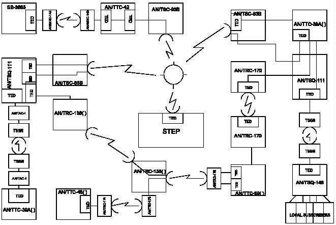 Figure V-2. Representative Joint Transmission Network
__________________________________________________________________
a. If traffic flows between AN/TTC-39()s via CNCEs and
AN/TRC-170s, bulk encrypt at the AN/TRC-170s.
b. If radio links are remoted via a TSSR or the
AN/TAC-1, bulk encrypt at the CNCE. If the AN/TSQ-146 is
being used instead of the CNCE, bulk encrypt at the
AN/TSQ-146 or at the ASOC.
c. The KG-94()/-194() TED has a number of internal
strapping options for various applications. Strapping
options for common applications are contained in Appendix G.
Figure V-2. Representative Joint Transmission Network
__________________________________________________________________
a. If traffic flows between AN/TTC-39()s via CNCEs and
AN/TRC-170s, bulk encrypt at the AN/TRC-170s.
b. If radio links are remoted via a TSSR or the
AN/TAC-1, bulk encrypt at the CNCE. If the AN/TSQ-146 is
being used instead of the CNCE, bulk encrypt at the
AN/TSQ-146 or at the ASOC.
c. The KG-94()/-194() TED has a number of internal
strapping options for various applications. Strapping
options for common applications are contained in Appendix G.
CHAPTER VI
DATA NETWORK SECURITY
1. General. As a JTF builds up, a tactical wide area
network (WAN) is established. The JTF WAN is composed of
Internet protocol (IP) routers (IPRs) and packet switch
nodes (PSNs) with protocol gateways to automatically route
traffic to and from local and remote subscriber local area
networks (LANs). Tactical-to-strategic connectivity is
achieved through Integrated Tactical-Strategic Data
Networking (ITSDN) gateways. The strategic networks to
which tactical users must be connected are the sensitive but
unclassified IPR network (NIPRNET), the SECRET IPR network
(SIPRNET), and the Joint Worldwide Intelligence Communi-
cations System (JWICS). (JWICS is not accessible via ITSDN
at this time). These networks handle traffic at different
levels of security. In the JTF WAN, data from all three
networks may traverse the same transmission backbone. This
could be accomplished through the use of the Network
Encryption System (NES) inline network encryptor (INE).
Specific security information about the NES is found in
Appendix H. More information about the network may be found
in CJCSM 6231.07A, Chapter VIII.
2. Security Policy Considerations for JTF to IP Network
Connectivity
a. Deployed JTF networks can access strategic IP
networks at the sensitive but unclassified (SBU), SECRET,
and SCI levels using the NIPRNET, SIPRNET, and JWICS
respectively. The connection policies are outlined below.
b. In support of the Defense Information Infrastructure
(DII), DISA is responsible for establishing the NIPRNET and
SIPRNET connection requirements, accreditation procedures,
and the subsequent publication of such policies to the
commands, Services, and Defense agencies. For JWICS, DIA
will provide cognizance over SCI connections on a case-by-
case basis until the process to standardize SCI connectivity
via STEP sites has matured.
3. NIPRNET Policy. The security connection policy for the
NIPRNET is currently under DISA internal review.
4. SIPRNET Policy. For potential SIPRNET subscribers
desiring connectivity, the following interim network
connection requirements must be met before a new connection
is granted. These interim procedures are considered valid
until the overall DII connection requirements are
promulgated by DISA.
a. Contact the SIPRNET Program Office. All CONUS
customers desiring a direct connection to the SIPRNET must
first contact the SIPRNET Program Management office,
DISA/D3113, at COMM (703) 735-3238/8290/8041, or DSN 653-
8290/3238/8041. European customers contact DISA-EUR, at DSN
(314) 430-8457. Pacific customers contact DISA-PAC, at DSN
(315) 456-2858.
b. Prepare System Security Package. For DISA to
approve SIPRNET connectivity, all automated information
systems (AIS) currently connected or desiring connectivity
must submit the following documents to the Defense
Information Systems Agency, Attn: D3113, 11440 Isaac Newton
Square, Reston, VA 22090-5087.
(1) Accreditation Letter. Signed by the cognizant
Designated Approval Authority (DAA) for the network or
system requiring connection to SIPRNET. If the AIS is not
accredited, indicate if system is operating under an interim
approval to operate (IATO). The SIPRNET connection will not
be granted unless accreditation or IATO is provided.
(2) Interim Approval to Operate. If an IATO has
been granted, advise DISA of all significant risks the
system is currently operating under. Significant risks
include lack of identification and proper access controls,
lack of audit function, unprotected connections to other
networks which are not approved to connect to SIPRNET,
unapproved connections to other networks.
(3) AIS Concept of Operations and Security Policy
or Equivalent Documentation. These security documents will
describe how security requirements have been implemented in
the environment. Further, these documents will identify
data types, classification level of date, system owner, and
designated approving authority.
(4) System Connectivity Diagram. This diagram will
identify all AIS connections, both front and backside, to
include any connections to other gateways directly or
indirectly connected to other networks. Diagrams will
include the applicable IP address.
(5) Foreign Connections. The SIPRNET is a SECRET,
SYSTEM HIGH, US ONLY, network. However, connections to
foreign government agencies may exist. All foreign
connections to the SIPRNET and applications to be used must
first be validated by the Joint Staff under the provisions
of CJCSI 6740.01 and CJCSI 6211.02A and approved in
accordance with this policy. All foreign connections will
require the installation of a high assurance guard device or
an end-to-end encryption device. Both types of devices will
be under US control (procured, operated, maintained, and
configured by the US sponsoring activity) and used to
prevent unauthorized or accidental disclosure of classified,
US ONLY information on the SIPRNET.
(6) Acknowledgment of Periodic Monitoring and
Vulnerability Assessments. All connection requests must
provide the following statement: "We acknowledge and
consent to DISA conducting an initial vulnerability
assessment and periodic unannounced vulnerability
assessments on the connected host systems to determine the
security features in place to protect against unauthorized
access or attack."
5. Application of SIPRNET Policy. DISA will review the
above documentation and make a connection approval
determination. The Joint Staff will validate and approve
all foreign connections. After reviewing the documentation
and ensuring initial security concerns are satisfied, DISA
will issue interim approval to connect to the SIPRNET for
180 days in most cases. The final approval will be provided
based on successful completion of a vulnerability assessment
and satisfaction of security documentation. SIPRNET
requests for service and feeder TSRs can be submitted
concurrent with the above documentation; however, connection
activation will not occur until an interim connection
approval is granted in writing.
6. SIPRNET Access Limitations. Failure to comply with
these requirements may result in service disruption. DISA
reserves the right to deny or discontinue SIPRNET access to
any network or system demonstrating behavior that increases
risk to the SIPRNET infrastructure and SIPRNET subscribers.
7. JWICS Policy. At the request of the J-2 DIA, JWICS can
provide JTF components SCI system-high access on a
case-by-case, contingency basis. In general, the following
preplanning considerations and security constraints need to
be addressed prior to a connection request:
a. Preplanning Considerations. Every JTF operation
requires planning for the following two categories of JTF
intelligence communications requirements:
(1) For the exchange of intelligence information
within a deployed JTF (intra-JTF exchanges).
(2) For the exchange of intelligence information
between the deployed JTF and organizations external to the
JTF (external JTF exchanges).
b. Information System and Communication Services
Constraints. In the past, planning support for intelligence
information flows for current or near-term operations has
been constrained by the limited capabilities of existing
intelligence information systems to communicate over data
networks. Therefore, DIA methodology for long-term planning
stresses that all intelligence information systems will be
able to communicate over data networks and that information
requirements can be combined to determine aggregate
requirements. However, current constraints dictate that
intelligence data that supports a JTF will be classified at
the SCI and collateral levels (normally SECRET), with
separate communication networks necessary to support these
different classification levels.
c. Future Options. Packet encryption techniques that
encrypt packets with a security level that is different from
the transporting network may offer a solution. Data with
multiple security levels can then be transported over one
communication system. Several successful initiatives have
demonstrated this capability. DIA methodology is designed
to incorporate such advances as they mature.
d. Current Policy. Until efforts to achieve end-to-end
flows of intelligence information from the national and
theater echelons down to the echelons within the deployed
JTF have matured, the DIA methodology specifies that
intelligence communications requirements will be specified
and implemented separately for each security level.
e. Summary. The DIA connection methodology uses a
framework developed for long-range planning for the
intelligence support area. The key component of the
methodology is a functional model for intelligence that
identifies the intelligence functions required to support
JTF operational requirements and determines the intelligence
information flows that support the functions. Advances in
packet encryption techniques may reduce the current
constraints on the communications planner. Prior to
addressing specific security communications service
constraints, contact the DIA Deputy Directorate for Crisis
Operations (J2O) office at (703) 614-5555 to obtain the
JWICS contingency deployment policy framework document that
outlines the full preplanning methodology.
Transcription and HTML by Cryptome.