Create one big shielding case full of electronics, fill two smaller shielding cases with electronics and make wires going from the cases and some mechanical accessories for all three cases according to the following guide.
If you would like to make PCB's, Karl Jan Skontorp has made PCB's and a guide how to make double-sided PCB's at home for Ronja 10M Metropolis.
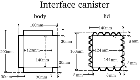
| Cut the big box (we assume the small boxes are bought as ready goods) from the tin as specified in the diagram and solder the body together in the corners. |
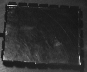 | Make several flaps on the lid as specified in the drawing. Bend each flap separately with pliers, first bend the whole flap and then bend the tip of the flap in opposite direction. Then try the lid on the case and adjust the flaps as necessary so that the lid is tight on every flap, but it is still possible to put it on and off the bottom. |
Solder together bottoms and walls of the smaller shielding boxes.
 | Remove the lid of smaller shielding boxes (receiver, transmitter) and cut the flaps with tin scissors so there are many small flaps instead of one huge. Make six flaps on the longer side and four on the shorter side. |
Mark a line in half of the height all around the four walls on both smaller boxes. Mark a centre of hole in the middle of longer wall on both boxes. It will be the front. Mark also centres of holes 30mm on each side from these. Drill out the central holes with 5mm bit (receiver) and 3.1mm bit (transmitter) and the side holes with 3.1mm bit on both boxes.
Mark holes on the shorter walls of small boxes. Each will be 8mm from the corner, on the long line marking the half height. Drill them out with 4.1mm bit (eight holes, four on each box). Mark one extra 3.1mm hole on the transmitter, between two of the screw holes. This will be for bolting the 7805 down.
Make 6mm holes on the rear of the boxes. On transmitter two holes for cable bushings. On receiver three holes for cable bushings.
Now drill also something on the big box: drill out one 8mm hole in centre of each shorter side of the box. Put the wire nut on the bottom of the big box, parallel to shorter side, in centre of the shorter side. Drill through the bottom where two end holes are on the wire nut. Screw the nut to the bottom with two M3x15 bolts and two M3 nuts. Let the bolt heads are inside the box.
Close the two smaller boxes. Wipe their front with dry clean rag to remove dirt and fat. Paint the outside of the boxes with the black matte water-soluble top coat paint. Wash out the brush, leave the paint to dry, then paint it once again, wash out the brush and leave the boxes to dry.
Place the M3 bolts into the thermal shield holes in front of the boxes, heads inside the box. Tighten them with nuts from the outer side. Then tighten them with additional nuts, so two nuts are in stack on the bolt.
Place the M4 bolts into the side holes (4.1mm), heads inside the tin box. Four bolts per one box. Do it for both boxes. Put there a nut and tighten. Put there another two nuts and tighten them against each other. The distance between the box and the outer edge of the outer nut must be (smoke_pipe_nominal-shielding_box_width-2)/2. So that distance between nuts on opposite sides is smoke_pipe_nominal.
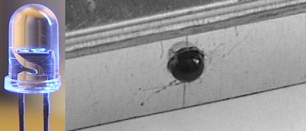 | Put the SFH203 detector in place and solder anode to the box. Bend the cathode pins of the emitter just at the case toward the dome, put emitter into place and solder the bent pins to the box with a piece of thick copper wire (to ensure good thermal conductivity for cooling). Put the cable bushings in place on all three boxes. |
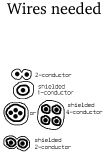 | Now we will
install the wires into the small shielding boxes. Cut three 25cm pieces of
shielded 1.5mm^2 two-conductor. Cut two 25cm pieces of the shielded
one-conductor (or max.4mm outer diameter coaxial cable). Strip all ends of
these conductors and cover them with a solder. Put the shielded cable into
the middle hole of the receiver and the hole on the transmitter that is on
the side on which less holes is drilled in the side (where bolts already
protrude). Put the remaining unshielded wires into the remaining holes.
Now we will install cables into the big shielding box. Cut one 10cm piece from the shielded two-conductor cord (or take two 10cm pieces from a shielded one-conductor cord) and 1m from the shielded four-conductor cable. Strip all ends and cover them with a solder. Solder four 4mm^2, 20mm long pieces of stripped hard wire on one end of the 10cm piece. Insulate the joints with a duct tape and choose the colours in a way it is obvious which is the shield and which is the inner conductor. Put both cables through the bushings. |
Seal all bushings, detector, emitter, cables with silicone sealant (don't hesitate to waste with it). Do not smudge the outer surface of the optoelectronical components with the sealant because it is nearly impossible to remove it. wait until it solidifies. Solder the 15-pin CANON connector on the end of the shielded 4-conductor, together with the 39R resistor, and cover it with the connector cover.
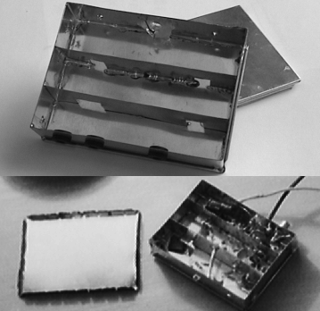 | Now we will furnish the inside of the receiver box. Take the 8mm drill bit and wind three 10-turn inductors on it. Use thick insulated copper wire. Cut two partitions from tin-plated tin along the longer side of the box. These partitions will form three narrow non-uniform compartments. The compartment near the bushings will be in 1/2 of the width, the other compartment in 1/4 of the width, so the widths of the compartments are in 1:1:2 ratio. Make two holes in each compartment. The compartment that will be near the bushings will have one hole through which the NE592 chip will protrude and second hole for a resistor. The other compartment (near detector) will have a hole for BF988 transistor and for a resistor. Solder the compartments in place. They will be in the receiver canister. |
Now we will furnish the inside of the transmitter box. Take M3x10 screw and M3 nut and thermally conductive paste and attach the 7805 regulator down the box. Place the screw head outside the box. Tighten. Put three 74HC04's on each other (like they are having sex) and solder them together.
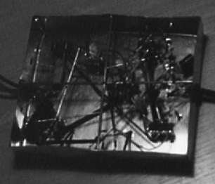
Now we will do the big soldering. Place the parts into the boxes logically, start placing from edge and move to the center. Do not make ugly loops or long wires to prevent oscillations. Don't let one signal go around the box. Place blocking capacitor (those over power pins) near the parts that are feeded by the power, as near to the part as possible. When placing the 2N3904 transistor pairs (those two transistors that are near in the schematic), do it this way: find the closest matching pair and put it into the receiver. Find the closest-matching pair from the reast and put it into the transmitter. If you can't measure the transistor, place them randomly.
 | Solder remaining parts into the interface. The schematic follows. |
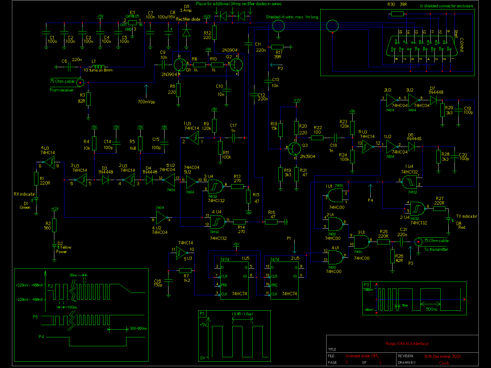
| Solder remaining parts into the transmitter. Put the three 74HC04's in stack (like they are fucking), and solder pins of equal numbers together. The schematic follows. |
![]()
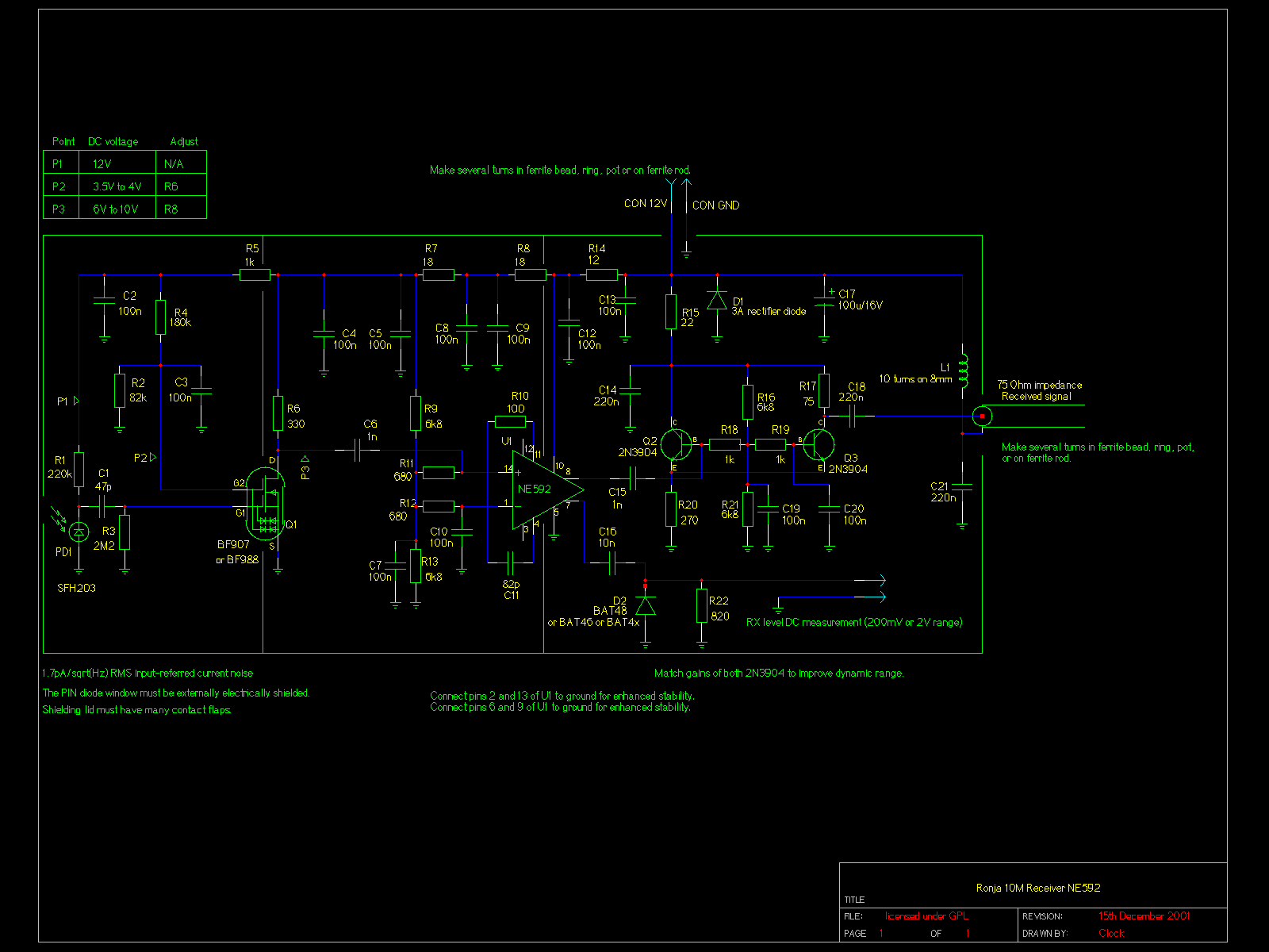
| Solder remaining parts into the receiver. The schematic follows. |
Now we will finish the wires and make some extra wires for interconnecting the two tubes together. Solder 20mm long 4mm^2 hard copper wire pieces on all ends of the receiver and transmitter wires and insulate them with the duct tape. Choose the colours systematically to be able to distinguish shieldings from cores of shielded cables and CON_12V from CON_GND in power cables,
Cut one 1m piece from the unshielded 1.5mm^2 two-conductor insulated cord (for shortpower cable bearing CON_GND and CON_12V) and one 1m piece from the unshielded 1.5mm^2 one-cuductor insulated cord (for short cable interconnecting heating) Also place the 20mm 4mm^2 pieces on their ends and insulate. Also choose the colours somehow logically.
Optional: place the EMC ferrite beads or cores near the ends of the double-conductor last made and tighten down with duct tape. The single-conductor is innocet from EMC point of view.
The electronics is ready now.
You can download here schematics in ".sch" format for gEDA gschem schematic capture editor (released under GPL) -- see gEDA homepage. There are several extra parts that (depending on the version of gschem) you have to install. Those are: NE592, 74(HC)132, dual-gate NMOS, photodiode, and aui connector.
There are part lists available for all three electronics circuits as well as a global part list: